In my last post, I described Oliver Lang’s unique
modifications to HMS Terror’s stern to accommodate the screw propeller. A
primary component of this modification was a massive 3.5 inch thick “iron
staple knee”, which securely bound the keel, original sternpost, and rudderpost
together.
To model this part, I will use brass, blackened to simulate iron. I originally attempted to bend and
hammer a 1.85 mm thick piece of brass into the correct shape, but try as I
might, I could not create the appropriate angles accurately and only produced a
mangled mess. Finally, I resigned myself to the fact that I would need to cut
three separate pieces and then silver solder them together. I had never attempted this before, but I found
a great deal of information on
Model Ship World, and decided to give it a try.
.JPG) |
| Brass stock cut to match the dimensions of the three sides of the knee. |
 |
| Preparing to drill the holes for the bolts. |
 |
| A rough jig necessary to hold the pieces in place while soldering. |
 |
| The drilled pieces. |
 |
| My new pen torch and other soldering equipment. |
 |
| Clamping the pieces to the jig. It was a tricky task not to burn the jig, but thankfully the joints were small and the brass heated rapidly. |
 |
| The knee after soldering. The joints are much stronger than I hoped they would be. |
 |
| The final part filed to shape and compared to the plans. |
 |
| An alternate view of the finished part. |
 |
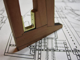
| The knee dry-fitted to the stern piece. |


.JPG)


No comments:
Post a Comment