Monday 4 November 2013

HOISTING TERROR’S COLOURS

HMS Terror’s paint scheme is considered to be well known. Richard Cyriax, who produced the most authoritative work on Franklin’s last expedition, states: “Both ships were flush-decked, and had black hulls, white masts, and yellow weather works...” (Cyriax 1997:39).  This passage has long been interpreted by subsequent researchers to mean that the ships had a yellow stripe along their outside hull (e.g. Parks Canada, Canadian Geographic, and published work too numerous to list here).  Cyriax based this description not on a primary source, but on a popular work by his friend, Rupert T. Gould (1928:112); unfortunately Gould appears to have misinterpreted the primary source material.

Gould’s information came from a remarkable parliamentary record, which documents an Admiralty investigation into two ships spotted trapped in an iceberg off the coast of Newfoundland in 1851 (Inglis 1852). The investigation focused on comparing the eyewitness testimony about the iceberg ships to the firsthand knowledge of the shipwrights who worked on Erebus and Terror. While the Admiralty determined that the iceberg ships could not be Franklin’s vessels (the size difference between the ships was too large and they were not barque-rigged ), the report contains critical primary information on the paint scheme of the Erebus and Terror from Oliver Lang, the master shipwright responsible for the 1845 refit of the vessels.  

The correspondence between Lang and the Admiralty is worth quoting here in its entirety (Inglis 1852:18):
 

Admiralty, 17 April 1852.
Sir,
I am commanded by my Lords Commissioners of the Admiralty to desire
you to call upon the officers of the yard under your superintendence to
report how Sir John Franklin's ships, the " Erebus" and " Terror," were
painted when they sailed.

 
I am &c.
(signed) J. H. Hay,
pro Secretary. 

Commodore Superintendent Eden,
Woolwich.
  

Woolwich Yard, 17 April 1852. 

Sir,
With reference to their Lordships' letter of this day's date, we beg to
acquaint you, that Sir John Franklin's ships, the " Erebus " and " Terror,"
were painted when they sailed, black on the outside, and weather works
inside yellow.

 
                                    We are, &c.
(signed)                         O. Lang,
Master Shipwright


Further information about the colour of the masts was also requested from Lang and appears below (Inglis 1852:35).

 
Admiralty, 2 June 1852. 

Commodore Superintendent at Woolwich, 
Referring to your communication of the 17th April last, upon the subject
of painting the " Erebus" and "'Terror," my Lords desire that you will state
for their information how their lower masts were painted. 

By command of their Lordships.
(signed) W. A. B. Hamilton.
                                                                                   
Woolwich Yard, 2 June 1852.

Sir,
Agreeably to your minute on Captain Hamilton's letter of yesterday,
we have to acquaint you that the lower masts of the "Erebus" and "Terror"
were painted white when they left this port. 

We are, &c.
(signed)                       O. Lang,
Master Shipwright..


H. Chatfteld, Assistant ditto.'
(Mr. Peake sick.)
The Commodore Superintendent.
Submitted for the information of their Lordships.
Henry Eden, Commodore Superintendent.
The Secretary of the Admiralty

Lang’s choice of words in the first correspondence appears to be the source of the enduring discrepancy regarding the ships’ paint schemes. It seems Gould, followed by Cyriax, and then myriad others, interpreted the phrase “weather works inside yellow” to mean a band of yellow on the outside hull of the vessel. Indeed, the “weather works”, or upper works of a ship, are those areas of the vessel above the waterline exposed to the weather, including the upper hull and bulwarks both inside towards the deck and outside on the hull. However, Lang specifically states that the “weather works inside “ were yellow, meaning that the inside bulwarks were painted yellow. He makes no mention of a stripe on the outside hull, although a solid paint scheme without a stripe would have been unusual for a Royal Navy vessel of the era.
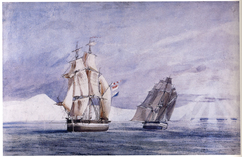
Thankfully, a watercolour painting by Owen Stanley, who accompanied the ships across the North Atlantic to Greenland in 1845, provides important primary evidence which dispels much ambiguity (see below). The painting shows conclusively that the Terror and Erebus had black hulls with a white stripe along the outside weather works. The painting indicates that the white stripe was contiguous with the chock channel and that it ascended the outside stern frame of the Erebus at an angle. Another watercolour, which may also be the work of Stanley (it is clearly based on his 1845 drawing), confirms these characteristics, and also shows the yellow painting on the inside bulwarks (note also the very rusted condition of the iron bow plating). This image also suggests that the white stripe extended forward around the knee of the ship.


Owen Stanley, 1845, "Signal to Terror, opportunity for sending letters to England, 4 June 1845", courtesy National Library of Australia.

The presence of a single stripe along the hull, which extended around the knee of the ship and up the exterior stern frames, appears to be confirmed in other contemporary sketches by Stanley, Gore (also here), and Fitzjames, as well as by the Illustrated London News (which also confirms the white stripe on the outside stern frame, see below). 


A white stripe painted on the exterior weather works is entirely consistent with Royal Navy standards of the mid-19th century. Yellow and black striping, or the “Nelson Checker”, was common in the Royal Navy vessels up to about 1815. However, after ca. 1815, Royal Navy vessels began to adopt the black on white pattern first established by the American Navy around the turn of the 19th century. In fact, black hulls with white stripes remained the standard paint scheme of Royal Navy vessels well into the steam era (see Konstam 2010 for good summary).  It therefore seems obvious, given all of the available data, that Erebus and Terror were painted with the standard white on black scheme of the era, which may explain why Lang didn’t deem it necessary to mention this standard attribute to the Admiralty.

Most Royal Navy ships placed the white stripe over the gun ports above the waterline; when opened, the ports/lids created the “checker board” pattern. However, all contemporary images of the Franklin ships show that the white band corresponded with the solid chock channels grafted on to the ships. It is important to note that this paint scheme is different than that utilized during the 1839 Ross voyage, where the ships appear to have had two bands of white on the outside weather works. A watercolor of HMS Terror by Davis shows that one of the white stripes was contiguous with the chock channels, as in the 1845 expedition, while the other white stripe was a little lower, perhaps contiguous with the band of copper sheathing that extended below the chock channels for most of the ships' length at this time.

The colour of the top, horizontal, surface of the channel is less certain, as the Stanley watercolours provide little detail in these areas. One of Stanley’s sketches (see here) seems to indicate that the tops of the channels were black, while another suggests they were potentially white (see here). However, the famous image from the Illustrated London News clearly shows that that the top of the channels were painted white (see image above). An image of the Terror beached on the Irish Coast in 1837 by Owen Stanley (see below) also shows that the tops of the channels may have been painted white (or at least a lighter colour), though how consistently the ships were painted on subsequent voyages is unknown. Since the paint scheme is ambiguous, I intend to try both versions on the model and choose whichever seems to fit better with the overall colour scheme of the ship.


Similarly, contradictory information exists about the paint scheme on the rudder and transom of the ships. The 1845 watercolour by Owen Stanley seems to show that the transom and rudder were painted black, although the lighting effects on the painting suggest that those areas of the ships may simply be in shadow. Other contemporary sketches by Stanley and  Graham Gore (also here) suggest that a lighter colour was painted on the stern window frames and on the entire transom of the ship, while the rudder remained black (perhaps with white trim?).  The Illustrated London News image is slightly different (see above), showing a thinner arch of white surrounding the windows of the ship and a darkly painted rudder.

Colour paintings of the Erebus and Terror produced for the Antarctic expedition by Davis (see also here) show that the entire transom was painted white and the rudder was black, again perhaps with white trim (although lighting might play a factor here as well). Interestingly, the Davis paintings also show detail of an arch-shaped feature surrounding the windows.  Similarly, a sketch of the Terror from 1837, by Owen Stanley, indicates that the transom was painted completely white (Back 1838:400).  A water colour of the Terror on the same voyage by William Smyth also shows an all white transom, this time with a white rudder.


On balance, the available sketches and paintings suggest that the transom was painted completely white, and that the window frames were as well. The rudder is more ambiguous, but again, the weight of evidence seems to indicate that it was painted black, perhaps with white trim (the Terror did have several separate trim pieces grafted to the aft margin of the rudder).  

I assume the black hull paint extended to the keel, as we know that HMS Terror and Erebus were not coppered below the waterline, as noted in The Times on 26th April, 1845:

 
“The decks of the Erebus and Terror are constructed on the diagonal principle,
and about twenty feet on each side of the bows has been cased with strong sheet
iron. There is not any copper sheathing on either of the vessels, as no danger is
to be apprehended from the attacks of shellfish or barnacles, the ice soon clearing
them from encumbrances of that description.”

                                                     (The Times, London, 26 April 1845)

This is in contrast with the Illustrated London News image of the ships which appears to show a copper plated hull, which must be an error.

One of the things I enjoy about ship modeling is that it is woodworking – often with very fine hardwoods. Like many ship modelers, I don’t want to cover beautiful wood with paint; instead, I intend to present the Terror’s historic paint scheme using minimally treated natural or dyed/stained wood finishes. My plan is to use dyed or stained Swiss pear for the keel, stem and stern timbers, and hull planking; holly for the transom, chock, and deck planking; and yellowheart for the inside bulwarks. I’ve order the material from Hobby Mill, all planed to exact scale thicknesses, which I will discuss in future posts.  My wood arrives in early December; until then, I will keep cutting stations!

References Cited:


Gould, Rupert T.
1928    Oddities. Frederick A. Stokes Company, London .

Inglis, R.H.
1852 Vessels in the North Atlantic. House of Common Parliamentary Papers, London.

Konstam, Angus
2010 Naval Miscellany. Osprey Publishing, Oxford.


Sunday 3 November 2013

STATION UPDATE


Over the past several weeks, another woodworking project has kept me away from HMS Terror. However, I’ve made a little progress on preparing the bulkheads for assembly. These are made simply enough; the station plans are glued directly to the plywood board using spray adhesive and then cut out using a scroll saw with a fine blade.

You can see from the picture that I’ve intentionally left a rough 1-2mm gap surrounding the plan outlines. It is impossible to cut the bulkheads accurately with the scroll saw, so they will be carefully reduced to the precise dimensions using a spindle sander and file. The midline slots will be cut with a coping saw, again to ensure accuracy.

If you look closely, you can see the shrewd eye of Crozier overlooking the outfitting of his ship (he’s 1:48 scale as well).

Thursday 17 October 2013

CONSTRUCTION PLANS

The construction plans laid out in my small workshop.

While I can never be certain that my plans are precisely correct, I believe, given the available historical sources, that they represent a reasonably accurate representation of HMS Terror as she was fitted for her final 1845 voyage. Certainly, much research remains to be completed on specific details (e.g. colour scheme, masting and rigging, hardware, name and cipher(?), etc.), but now that I’m satisfied with the accuracy of the ship’s general profile and dimensions, I can move to creating construction plans for a plank on bulkhead model.

I created the plans directly from the inboard profile and body plan, using a method similar to that outlined by Rich Brayshaw. The stern configuration from the sternpost to the rudder will be recreated just as it was designed in the Terror’s 1845 stern modification plan, and the keel, false keel, stempost, stemson, and knee will be constructed in a similar manner. The false keel structure will be made from 1/4 inch (6.35 mm) plywood, which matches the exact scale width of the sternpost and keel. The slots in the false keel descend to the load waterline, and will accommodate 21 bulkheads, corresponding to each station on the plan. While this might seem overkill for a 1:48 scale model of a small ship, it will give a very solid base for the planking, and I believe it will generally result in a more accurate model. You may notice that the height of the false keel doesn’t line up exactly with the inboard profile plans; this is because I modified it to account for the deck camber (derived from the 1839 Terror and Erebus cross section plan).


Note: This plan has intentional errors to discourage commercial copying. 


The bulkheads (which represent all the stations) may seem quite unusual to those who work with plank on bulkhead models. This is because each includes a precisely faired outline of the solid chock channels that surrounded the ship. The 1839 Terror and Erebus cross section plans show that the channels actually sat on the first layer of planking, and I considered recreating this, but quickly dismissed it. My reasoning is that, after a first layer of planking, it would be very difficult to line up the channels to create a perfectly symmetrical model. As a result, I’ll apply the first layer of planking around the chock channels (they will actually help me align it), then plank the channels, then apply the second layer of planking (recall that both the Terror and Erebus had double deck and hull planking). The bulkheads will be cut from 5mm plywood.

Note: This plan has intentional errors to discourage commerical copying. 

 There is something very tangible to me about rolling out a freshly printed sheet; the plywood is now being pressed to remove any bends and twists; cutting starts this weekend!

Sunday 6 October 2013

PROOFING THE PLANS: PART II – THE LOCOMOTIVE ENGINE

One of the major innovations of the 1845 expedition was the conversion of HMS Terror and Erebus to auxiliary steam power (Battersby and Carney 2011).  On his blog, Peter Carney has documented his research on the locomotive engines used in this conversion; he later published his findings in the International Journal for the History of Engineering and Technology (Battersby and Carney 2011). To me, his research strongly indicates that the locomotive engines were not the Planet Type as has traditionally been assumed (e.g Cyriax 1997), but rather the Croydon and Archimedes engines built by G & J Rennie in 1838 and 1839.

 
Based on Carney’s research, I originally utilized a plan published in Brees (1840:133) which was labeled as the “Croydon” engine. However, in a recent email correspondence, Mr. Carney pointed out that this image was probably incorrectly attributed by Brees. The issue lies in the wheel arrangement and cylinder position. The image I based my locomotive plans on depicts a “0-4-2” engine with outside cylinders, while the Croydon was likely a “2-2-2” engine with inside cylinders (Bradley 1963; see also Carney’sblog). Mr. Carney believes the image I based my plans on probably depicted the “Hercules” engine, which was an assistant engine while the Croydon and Archimedes where passenger locomotives.

 
I always suspected there was something wrong with the locomotive I used in my original plans. If you look at my previous profile plans, the cylinders actually overlap the position of the spare rudder. Given that the modifications to the 1836 Terror plans show the exact position of the new engine room walls, this obviously could not have been the locomotive installed in 1845 (i.e. the locomotive was simply too big). Mr. Carney kindly pointed me to another image drawn by Brees (1840:306) which is unnamed, but which depicts a 2-2-2 locomotive with inside cylinders that was built by G & J Rennie – a good candidate for Croydon or Archimedes.


Using this new plan and an excellent set of drawings that Mr. Carney created and kindly provided (see his 3D reconstruction), I created my own scale plans of the locomotive. Using the dimensions from Bree’s (1840:14) original report, I scaled this new plan to exactly 1:48 and placed it in the proper position. As you can see, it fits perfectly, with just inches to spare on either side of the engine. To me, this exact spatial correspondence just adds credence to Carney’s theory that Archimedes or Croydon was the locomotive installed on HMS Terror.  

 
My new plans of the G & J Rennie engine, based on Brees (1840:306),
following the research of Peter Carney. The frame is speculative.  


INCORRECT - My original plan using the Hercules (?) engine. Note
the overlap with the spare rudder.
 

CORRECT? - The new engine in my updated plans.
 
Because of the new locomotive engine, the position of the funnel and steam outlet changed significantly, and these are depicted on the new deck plans. Given that the locomotive was only used in calm conditions or to avoid beating, it is likely that the chimney and steam pipe were removable, to conserve space on the crowded deck (Battersby and Carney 2011:202). As a result, I believe a scuttle or hatch system was used when the chimney was not installed, and I based these on one shown in the 1836 Terror deck plans (I have been unable to determine what that 1836 hatch was originally used for – the furnace chimney was apparently installed at the fore hatchway).


The positions of the chimney, steam pipe, and their hatches on my old plans.


The positions of the chimney, steam pipe, and their hatches on my new plans.

Finally, I should note that on my plans the height of the engine’s chimney and steam pipe are based on the following contemporary description (which also accurately describes the location of the chimney and the steam pipe):  


*  Note: Rather than post yet another set of updated plans, I’ve simply updated the plans on a previous blog post. The images have begun to be indexed on search engines and I don’t want to create confusion!


References:


Anonymous,

1845    Literary Gazette Journal for the Year 1845. Robson, Levey, and Franklyn, London.


Battersby, William, and Carney, Peter

2011    Equipping HM Ships Erebus and Terror, 1845. International Journal for the History of Engineering & Technology 81(2):192-211.

 
Bradley, D.L.

1963    Locomotives of the South Eastern Railway. Solihull: Railway Correspondence and Travel Society (1):11–12.

 
Cyriax, Richard, J.

1997   Sir John Franklin's Last Arctic Expedition: The Franklin Expedition, A Chapter in the History of the Royal Navy. The Arctic Press, West Sussex.


Tuesday 1 October 2013

PROOFING THE PLANS: PART 1 - CONTEMPORARY IMAGES

Over the past several months I’ve received some great feedback on my research into HMS Terror from the model shipwrights on Model Ship World. However, before finalizing the construction sheets, I felt that that it was important to ask the opinion of some Franklin expedition historians.


A few weeks ago, I took the opportunity to contact two of the most knowledgeable experts on HMS Erebus and Terror, William Battersby and Peter Carney. Both maintain their own blogs and have published on the ships in peer-reviewed journals (Battersby and Carney 2011). Moreover, both are true gentlemen; they kindly took the time to read through my blog and offered some very useful advice on my plans.


Mr. Battersby suggested that I look again at a drawing from the Illustrated London News (ILN) which depicts Franklin’s cabin on HMS Erebus. He pointed out that there appears to be a cabin stove with a straight chimney on the extreme left of the image, which I did not include in my plans. The image seems reasonably accurate; the number and position of the windows and the shape and size of the stern lockers and superstructure matches the 1839 plans perfectly. As a result, I’ve modified my plans to include this stove; I based its dimensions and shape on what can be deduced from the image. The chimney for the stove is based on an 1839 image of a cabin stove available from the National Maritime Museum archive, and the height of the chimney is based on tables from Lavery (1987:291). Incidentally, the height of the chimneys for the ship’s stove and furnace are based on information in Lavery’s book as well.

 
Cabin stove and chimney detail.


Mr. Battersby also reminded me that a (very early) 1845 daguerreotype image of one Franklin’s officers, Lt. Henry le Vesconte, was taken on the deck of HMS Erebus. I’ve scrutinized it many times before and it’s a remarkable image which should be included in any blog about the ships. Le Vesconte is sitting on the starboard side of the Erebus (note the image is often shown backwards) next to the compass table in front of the mizzen mast. The photo confirms that the position and design of the skylight, mast, and wheel remain unchanged from the 1839 plans, and may also show part of a small deck house further aft on the starboard side (it appears to have a black door).


Mr. Carney also provided some extremely helpful insights. He pointed out that another image from the ILN shows two white deckhouses at the stern of both ships (note they also have black doors, just as in the Le Vesconte image). These were most likely water closets and signal lockers, and in my original plans I kept these quite low (almost the height of the bulwarks), based on an 1845 image of Erebus drawn by Owen Stanley. However the perspective used in his sketch probably foreshortens the height of the deckhouse and is not a reliable guide. 


Following the ILN image, I modified the deckhouses to be the same height and size as the single deck house shown in the 1839 plans. It is unknown if both were water closets or if one was a locker of some sort, so, in keeping with the original 1836 and 1839 plans, I am assuming that only one water closet was built for this voyage (only one water closet was used on Terror’s first two voyages, and the Terror had roughly the same crew compliment on all three polar voyages). I placed the water closet on the starboard side, following the suggestion of Battersby and Carney (2011:204) and based its design on the 1839 plans. I turned the other deckhouse into a locker for signal flags and other equipment and I admit its interior design is entirely speculative. Regardless, the model will have single black doors facing forward as is displayed on the ILN image (and which appears to be shown in the Le Vesconte daguerreotype). I should also note that both HMS Investigator and HMS Enterprise (1848 Franklin search vessels) shared many design similarities with the Franklin ships and both had twin deckhouses roughly the same size and shape as I have shown on my plans. In fact, both of their deck plans show the water closet on the starboard side of the vessel.


The new deckhouse profile, based on the 1839 plans.


Detail of stern water closet and signal lockers.


I should note that Peter Carney has also produced an excellent 3D model of James Fitzjames’ cabin, based on another contemporary image from the ILN. I did not include this structure in my plans as it was never depicted in any of the profile sheets (it is shown on the deck plans).  

Finally, I must point out that the daguerreotype discussed above isn’t the only one that might show part of the ships. William Battersby has provided some interesting analyses of reflections in James Fitzjames' cap, which reveals some interesting details of one of the ships. Russell Potter, another Franklin blogger, has also written some very interesting posts about the reflections in the highly polished caps of the Royal Navy officers, which show the rigging and perhaps the ship’s boats (compare the reflection in the cap to the position of the ship's elevated and upturned boats near the mizzen in my profile plans). 
 

*  Note: Rather than post yet another set of updated plans, I’ve simply updated the plans on a previous blog post. The images have begun to be indexed on search engines and I don’t want to create confusion!
 

References:

Battersby, William, and Carney, Peter
2011    Equipping HM Ships Erebus and Terror, 1845. International Journal for the History of Engineering & Technology 81(2):192-211.


Lavery, Brian
1987    The Arming and Fitting of English Ships of War, 1600-1815. Conway Maritime Press, London.

Saturday 7 September 2013

HMS TERROR PLANS – UPDATED!!

As discussed in the previous post, here are the updated (hopefully complete?) plans for HMS Terror. Note that the Upper Deck Plan has been modified to include the accurate width of the propeller well, based on information gleaned from the engineer’s model. Also, I noticed that the stern model includes a narrow lip surrounding three sides of the propeller well (I assume for the scuttle to rest on), so that lip has also been included in my new upper deck plans.


RETHINKING HMS TERROR’S STERN

Over the past couple of weeks I’ve been designing construction plans for my model (I hope to begin cutting wood next week). As I worked on individual stern components, I began to notice possible errors in my plans. Specifically, the original 1845 stern sheet (and the annotations on the 1836 sheet), on which my plans are based, only exist in profile and therefore don’t show all the necessary cross-sectional modifications to the stern that were required. The problem lies exclusively in the well that was constructed to ship and unship the auxiliary screw propeller. If the rudder post (also known as the “false sternpost” or “after sternpost”) was the same width as the sternpost depicted in Terror’s original 1813 plans, there simply would not be enough space for the propeller well positioned directly in front of it. I strongly suspected that the rudder post was thicker than I originally drafted in the body plan (and thicker than the keel), but there were no historical plans that confirmed this. Fortunately, an engineering model of the modified stern was produced for the Erebus and Terror ca. 1845.


As can be seen from the model, the upper part of the rudder post was indeed widened, apparently by adding two large bolsters on either side; it then tapered abruptly at the opening for the propeller (likely to prevent drag). The added width on the upper part of the rudder post provided the necessary space for the propeller well and I’ve now changed my body plan to reflect this. However, in scrutinizing the stern plans and annotations to solve the width problem, I also noticed some faint modifications that I missed in my initial tracing of the plans.

First, the opening for the propeller well apparently included two separate iron fittings which were bolted to the rudder post and the sternpost, respectively. Each fitting appears to have had a groove which accepted a smaller rectangular metal frame which held the propeller (e.g. Battersby and Carney 2011: 204; 208). Guided by the metal grooves, the propeller frame could be raised or lowered into position using standard ship’s tackle. A contemporary example of exactly this sort of removable propeller system is preserved in a model at the National Maritime Museum in Greenwich (see here and here for similar designs).


My reconstruction of the propeller frame and chock system (profile and cross section).
The series of chocks were used to strengthen and protect the stern when the propeller was unshipped.


The propeller frame as it would have been installed.

Second, it appears that a unique u-shaped iron fitting, the same length as the propeller well, was used to secure the sternpost, keel, and rudder post to each other. Two or three large bolts secured a separate timber to each of the three faces of the fitting, effectively creating one solid structure. I suspect that this was a midline fitting which was protected and covered by a large fitted wooden chock, which itself was bolted to the surrounding wood, probably with as many as four bolts. Why this unique fitting was necessary has not been described in the historic literature, but is seems certain it was used to increase the strength of the sternpost near the keel (recall that Back’s voyage proved how vulnerable an unmodified stern could be to pack ice). How the ship’s stern timbers were attached to this structure is also not described, but it seems logical that the rudder post and sternpost would have been bolted to the two central stern timbers, with which the widened sternpost would have been contiguous. Contemporary models show that a sturdy rectangular frame enclosed similar contemporary propeller wells, and the sternpost and rudder post were also bolted to this frame.


The "U" shaped bracket and series of bolts used to attach the rudder post and sternpost to each other and the keel.

References:
Battersby, William, and Carney, Peter
2011 Equipping HM Ships Erebus and Terror, 1845. International Journal for the History of Engineering & Technology 81(2):192-211.