Sunday 4 December 2016

A WINDOW ON HMS TERROR

There are few secret places left to be explored in the world; but there is one waiting under the waters of Terror Bay.

The announcement that HMS Terror was recently found "in pristine condition" is astonishing, yet the revelation that the ship's stern lights (stern cabin windows) have survived intact is especially poignant.  Behind those 171-year-old stern lights is the very definition of a secret space; the cabin where Captain Crozier received reports and dispatched orders; where he entertained Franklin, Fitzjames and his officers in the better days; and where he huddled over his charts, plotting and planning his men’s desperate escape from the ice.

By 1845, Terror’s stern windows were very different from those Captain John Sheridan gazed through as he bombarded Baltimore in 1814. In 1812, Henry Peake designed a relatively traditional stern gallery for HMS Terror, which included seven stern lights in addition to six windows arranged on her port and starboard quarter galleries. Each of the stern windows had nine panes, while the smaller quarter gallery windows had six panes.

Henry Peake's original 1812 design for Terror's stern gallery and quarter galleries.
NMM, ZAZ5662

When Terror was first converted for polar service over 1835 and 1836, its vulnerable quarter galleries (and the water closets they contained) were removed, resulting in a reduction to five stern windows. Contemporary artwork by Owen Stanley indicates that the windows retained their original nine-pane configuration during Back's harrowing Arctic expedition of 1836-1837.


Terror's stern lights in 1837. Note the cipher and ship's name depicted above the hanging rudder.
 NMM, PAF0275

Since the time of Parry’s second Arctic voyage, 24 years previously, polar exploration vessels had been fitted with "double window-frames" (1), and Terror undoubtedly had double windows installed for Back’s 1836 -1837 Arctic voyage. Parry described that during the coldest months, "cork shutters" were inserted between the sashes on HMS Hecla (1), and it is possible that cork shutters were used on Terror’s subsequent polar voyages.

Contemporary images suggest that Terror's stern gallery remained unchanged during the Antarctic expedition of 1839-1843, when Terror was under the command of Francis R.M. Crozier, although the 1839 Terror and Erebus plans indicate that significant changes were made to the great cabin itself.

In the spring of 1845, Terror and Erebus had their sterns dismantled and reconstructed to accommodate large wells needed to raise and lower their new screw propellers. The centre window on the stern of each vessel was removed to make room for the new well. Green-ink annotations on Terror’s 1836 plans show that her stern frames were shifted slightly forward during the 1845 refit. The reasons for such an extensive refit are unclear, but it may have been necessary to redesign the stern framing to accommodate the weight and stress of the new propeller system.

While it appears that the remaining four stern windows were kept (roughly) in their original positions in 1845, the windows themselves were redesigned from a nine-pane to a four-pane configuration. We know this because of a remarkable woodcut of the great cabin of HMS Erebus, which appeared in the May 24th, 1845 issue of the Illustrated London News (2). The accompanying article described that the windows were “double[d]”, similar to those used on Parry’s voyages. Astonishingly, high resolution images of the cabin illustration in the report clearly show the double sashes.


The Great Cabin of HMS Erebus, as depicted in a woodcut
from the May 24th, 1845 edition of the Illustrated
London News


Why the stern lights were modified to a four-pane design is unknown, but the woodcut indicates that by 1845 the window muntins were much more robust than those on a typical stern window. A sturdier design might have been thought necessary, after the unprecedented heavy seas and storms Terror and Erebus encountered during their Antarctic expedition.  However, we know that the thickness of the glass was not increased, because window glass recovered from HMS Erebus in 2015 has the same  thickness as that specified on Terror’s (i.e., Belzebub’s) original 1812 building contract (3).

Below, I’ll outline how I have recreated Terror’s windows for my model. Though few pictures have been released, they appear to compare well with the recent Parks Canada images of Terror’s stern. The great cabin on the other side of those windows was the nerve-center of the living ship, where all the achievements, misfortunes, and decisions of the expedition were debated, decided, and recorded. In the coming years, it is a place where all the expedition’s mysteries may be revealed.

References:

(1) Parry, William Edward. 1824. Journal of a Second Voyage for the Discovery of a North-west Passage from the Atlantic to the Pacific: Performed in the Years 1821- 22-23, in His Majesty's Ships Fury and Hecla, Under the Orders of Captain William Edward Parry, R.N., F.R.S., and Commander of the Expedition. London.

(2) Departure of the “Erebus” and “Terror” on the Arctic Expedition. Illustrated London News, May 24th, 1845. Volume 6, Page 328.


(3) National Maritime Museum, ADT0010


Construction of the stern windows began with laser cutting the
sashes from a sheet of Swiss pear. 

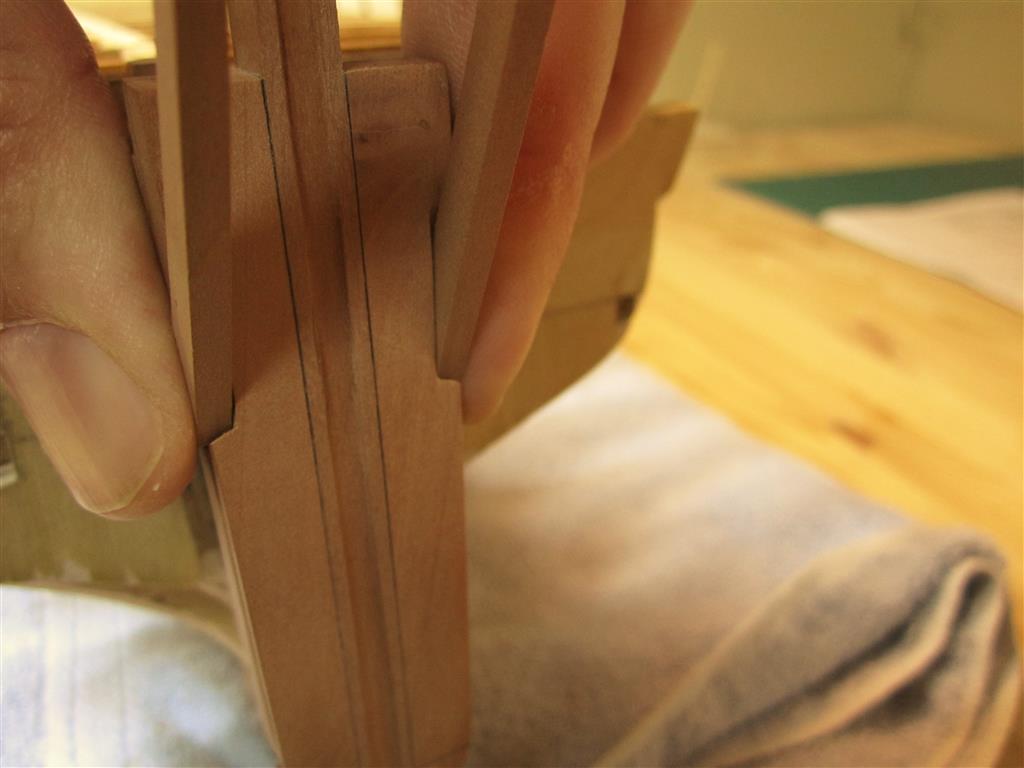
A bevel was added to each muntin with a hand file. The filed
windows are on the left, the unfinished windows are on the right. 

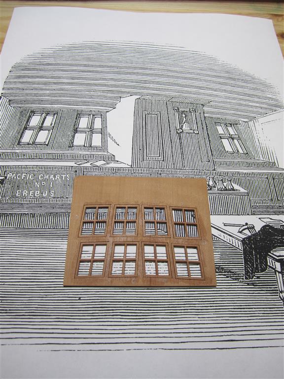
Comparing progress to the original woodcut. 

Instead of adding four individual panes, I opted to add a single simulated pane.
This was achieved by carving out the backside of the windows to
accept the simulated glass. 

The window panes were made from high quality PVC blister packaging material.
It is crystal clear, resists yellowing, and bonds well with CA glue. The painter's
tape protects the surface from scratches and permits patterns to be drawn
on the surface. 

A beading line of CA was used to glue the panes in place. 

Allowing the glue to dry. 

A pair of finished windows compared to the woodcut. Note the double
sashes in the woodcut image. 

Gluing the sills to the sashes. These are not the proper configuration,
but will not be visible on the finished model. 

A nickle for scale. 


The completed double windows.  

A closeup view.

The interior panes were sanded to simulate frost (and to prevent a
view into the interior of the model). 

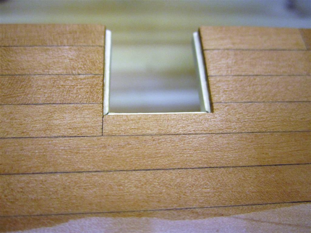
The port stern lights installed between the stern frames. 

A view from the interior of the model. The imposing nature of the
well can be seen here.  

Approximating the view from the great cabin
(as best possible).

The completed stern gallery. 

Mini-Cozier surveys the pack from the comfort of his great cabin.  


Sunday 18 September 2016

PLANKING TERROR'S TOPSIDE

Over the summer months, I have been working steadily on my model's topside planking, while it seems the real Terror has been biding her time, waiting to reveal herself to the world. Despite the excitement of the discovery, my work continues, though perhaps with somewhat more adrenaline than previously.  

I began this part of the project by cutting out the numerous ports on Terror's bulwarks, and then proceeded with planking the entire topside down to the level of the chock channels. The planking followed a carefully laid out plan that I devised for the entire model. 

Based on data in 1845 stern plans by Oliver Lang, the strakes on my model Terror vary between nine and ten scale inches wide whenever possible. Consistent with information gleaned from the original ship's contract, each strake is approximately 24 scale feet long (where possible), and follows a three plank shift. Deviations from this plan were necessary in many portions along the topside, where ports interrupted the normal planking layout (and common sense indicated a butt would not be necessary).  


I marked the position of the port sills using paper guides (this is the reverse
of the printed plan, used on the port side)

Each port was carefully cut out with a sharp blade. 

The port sills were lined with holly. 

Terror's bulwarks were riddled with ports. Here the bitts have been modeled
from Swiss pear and are portrayed in an unworn condition. 

Details of additional bitts. 

In the stern, Terror had two large chocks on each side. These were cut from Swiss
pear sheet stock and the correct shape transferred to them from a card cutout. 

Ensuring the chocks are symmetrical.

The finished pieces. 

And again after installation. 

Planking began at the solid ice channels and proceeded  strake by strake (tier by tier), following the
plan I had devised. Terror has an extremely bluff bow, and care had to be taken here. While spiling
would be preferred, I am constantly worried about my wood supply and used a technique taught
by Chuck Passaro. It worked very well, despite planking in scale thickness (here 4").

The port side, after a coat of Minwax Wipe on Poly. Note the bottom
strake is left untreated so that I can glue the ice channel top to it. 

Comparing the symmetry of planking on both sides of the knee. Following
the planking plan and marking off the hull carefully ensures
less variation. 

Terror's bow is so bluff, and the scale plank so thick, that I resorted to using a plank bending tool
to achieve the proper curvature. I dread planking the second layer on the wales, which
are over 9 scale inches thick!  I expect hot water immersion , or hot iron bending,
will be my only option there. 

Planking surrounding the many ports at Terror's bow. 

The planking plan indicated that one plank, in particular, would be very complex.
I measured and marked it off carefully before cutting. 

Installation involved dry fitting, careful sanding, dry fitting again, sanding again, and
repeating constantly until it was acceptable.  


Planking amidships, showing the three plank shift. 


Detail of the chocks after planking. 

The completed planking run on Terror's starboard side. 


The next task in my project will be to frame the stern lights (windows) and install them. Until then, I hope we get to see more images of the real ones from Franklin Expedition 2016. 


Monday 12 September 2016

HMS TERROR FOUND!

(Left) HMS Terror's wheel, found this week off King William Island.
(Right) The wheel from my Terror model. 

News came today that HMS Terror was discovered on the south coast of King William Island, in the aptly named Terror Bay.  Parks Canada is attempting to validate the discovery and I’m eagerly awaiting their assessment.

I’ve received many questions about how I feel about the discovery and what it means for my project.

In terms of my project, it is a wonderful thing, as was the discovery of Erebus. I’ve followed the plans and historical data very closely and now we get to see how it all compares. It can only lead to a more accurate model and plan, though I admit that the images I’ve seen so far don’t raise any alarms.

But, how do I feel? In a word, I’m elated.

I’ve been working on this project since 2013; I’ve studied and admired her formidable career; I’ve scrutinized every plank and bolt on her plans.

In my mind, I’ve spent nearly as many days on Terror as her men did. The thought that she may have been milled to splinters as they watched haunted me, because she (and her crew) didn’t deserve that fate. And frankly, it didn’t fit with what I knew (mostly in my heart, until now) of Terror.  I didn’t think she would have given up like that, even in that grinding pack off King William Island.

So the news that she sits on the sea floor, “in pristine condition” with her ”hatches closed and everything stowed” means everything to me. First it means that she actually made it – she essentially found the Northwest Passage. More importantly, it means that she took everything the Arctic pack could throw at her; that she sheltered her men to the very last; that she didn’t abandon them to the ice. 

There was nothing more anyone could have asked from Terror.  

That she survived it all in “pristine” condition, well, she deserves it.  She warrants all the attention, all the photographs, all the books and articles that will be written, all the documentaries and shows, all the accolades. 

She’s the greatest polar exploration vessel the world has ever seen. 

Wednesday 29 June 2016

GETTING PUMPED FOR TERROR’S BIRTHDAY

Today marks HMS Terror’s two-hundred and third birthday - the anniversary of her launch in Topsham, Devon on June 29th, 1813. Within a year of her launch, Terror would be harassing American cities along the Eastern Seaboard, and would even have an epic poem written about her exploits by Francis Scott Key. Today, when Americans sing their national anthem, they reference the history of our favorite exploration vessel.

This date also marks the third anniversary of the start of the Building HMS Terror blog, and today we’ll be celebrating our respective anniversaries by discussing Terror’s pumps.

By 1845, Terror had at least five pumping mechanisms installed, though it likely had other moveable “fire pumps” as well. For her size, Terror had a relatively large number of water management devices. Comparing the 1836 upper deck and profile plans of Terror to the 1839 plans shows that an additional two common pumps were installed just behind the forehatch, while the main pumps flanking the main mast were upgraded and replaced. 

These changes were likely a response to the near sinking of Terror during George Back’s arctic expedition of 1836-1837. In the spring of 1837, ice damage to Terror’s sternpost and keel created leaks so severe that five feet of water gushed into her hold every hour. Back ordered his men to work the pumps continuously during Terror’s return voyage across the Atlantic. The crew became so exhausted that they had to beach the vessel at the closest landfall, at Loch Swilly in Ireland.

Rice, the shipwright responsible for Terror’s 1839 refit, responded to this near disaster by upgrading all of Terror’s pumping systems. He also introduced penstocks into the limber board system in the hold, which allowed the crew to manage the flow of bilge water into her well.

Below, I’ll discuss each of Terror’s new pump systems in turn.


Massey’s (Massies) Patent Pumps (Bilge):


Massey’s patent pumps were a reliable flywheel pump system of a type that became very popular on civilian and navy vessels in the latter half of the 19th century. Testing of Massey’s pumps began in 1833 and timed trials on board HMS Thunderer showed clear advantages over traditional chain pumps. Water discharge rates over short durations were similar to the chain pumps, but at greater periods of time, the Massey pumps outpaced the chain pumps significantly (1). The main advantage of the flywheel design seems to be that “it [did] equal work with less fatigue to the men” (1). The trial was so impressive to the Admiralty that they installed Massey’s pumps on HMS Vestal in 1834 (2), and increasingly on Royal Navy vessels thereafter.

Massey’s pumps were a double action “lift and force” pump, consisting of a camshaft driven by two crank handles. The camshaft drove two 18 inch piston rods that powered the pumps. A heavy iron flywheel was mounted on the fore end of the camshaft, and, once in motion, it assisted in maintaining the momentum of rotation (thereby making the crank handles easier to turn). Unlike chain pumps, Massey’s pumps were very difficult to  clog, and could “…discharge a block of wood 9 or 10 inches in diameter”(1).  This was obviously the perfect pump for an arctic expedition vessel.

My plans for the Massey pumps on board Terror are derived from measurements shown on the 1839 plans of Terror and Erebus, with additional information gleaned from the somewhat more detailed HMS Investigator plans. Cross sectional details, especially of the fly wheels and piston rods, were derived from historical images of similar flywheel pumps, as I was unable to locate the patent for Massey’s 1833 pump design.

Plans for Massey's Patent Pumps, as installed on HMS Terror in 1839.


Common Pumps (Bilge):


Terror was fitted with two common, or suction pumps, also known as "elm tree pumps" due to the use of a single bored-out elm trunk as their barrel or tube.  Elm was used because of its general resistance to water, though other water-resistant woods could be employed. The pumps were extremely simple, consisting of a brake (or handle), a spear (or piston) and two valves, and were thus very easy to make and repair. The advantage of placing two common pumps in the fore of the ship was that the fore hold could be pumped out independently of the rest of the ship; which could be critical in a situation such as Back found himself during the 1837 Atlantic crossing.


Plans for HMS Terror's common pumps, as installed on HMS Terror in 1839.


Truscott’s Pump (Fresh Water):


Truscott’s pump was a simple invention that revolutionized the way water was stored and retrieved on Royal Navy vessels. Inspired by a visit to an ale house in 1812 (3), Truscott designed a relatively simple iron pump attached to a small diameter pipe system that led to the hold. Just like in the ale houses, he attached a flexible leather hose to the end of the pipe and fed it into the water casks. This obviated the need to move the casks to retrieve water. This was a major boon on sailing vessels, because moving casks to retrieve water was time consuming, dangerous, and inevitably impacted the ship’s trim, requiring periodic rearrangement of the ship’s casks and ballast. This simple invention eventually led to the use of permanent iron water tanks on sailing vessels, which ultimately resulted in the abandonment of shingle and iron ballast.

A plan of Truscott’s pump (ZAZ6848), dated 18th September 1814, is held by the National Maritime Museum.  The 1839 lower deck plan for Terror and Erebus indicates that one Truscott pump was located at the rear of the ship’s stove, on the starboard side, close to the door to the sickbay.  This pump permitted the crew and the ship’s cook to access fresh water as it was need. Since the water tanks in Terror’s hold surrounded the Sylvester stove/furnace, it is possible that the device could have be used throughout the winter months.  However, it is likely that the fresh water tank above the Fraser stove provided enough for the ship’s needs without using the hold tanks (at least during the winter months when fresh water ice was available).  

Truscott's pump (in red) as installed on HMS Terror in 1839.
The ship's water tanks and Fraser's stove appear in blue. 


References:


1. The Nautical Magazine: A Journal of Papers on Subjects Connected with Maritime Affairs in General. 1833. Page 292.

2. Sharp, James. 1858. Memoirs of the Life and Services of Rear-Admiral Sir William Symonds, Surveyor of the Navy from 1832 to 1847. Longman Brown Green Longmans & Roberts, London. Page 153.


3. Transaction of the Institution of Architects. 1865. Page 191.

Monday 30 May 2016

MY FAIR TERROR


“Fairing” is an important step in constructing an accurate hull shape on a ship model. It involves sanding and beveling the bulkheads to create an even surface for the planking to sit flat against the hull frame.

For my build, this was an extended process that allowed me to learn much about the construction of Terror and Erebus, especially at the stern and the bow.

In this post, I will present a photo essay documenting the steps I took to prepare the hull for planking. As I progress through the steps, I'll discuss what I learned about Franklin’s exploration vessels. 


Before I could begin faring the hull, it was necessary to fill in the
stern and bow of the model using filling blocks. I created these
from 1/4" plywood, laser cut using measurements from the
ship's plans. This image displays the three starboard filling
blocks used at the bow. 

The filling blocks were carved to shape using card
guides cut to match the lines of the half breadth plan. 

Placing the filling blocks side-by-side as they were carved ensured that they
were symmetrical. The lamination in the plywood was also helpful
 in this regard. However, plywood is a poor carving material,
and I would think twice about using it again. 

In 1839, the solid chock (ice) channels on Terror were extended around the bow. I
constructed these from several layers of basswood. 

These chocks were then shaped to match the proper cross section of the channels. 


The ice channels were glued in place on the bow and scrap wood 
was used to rough out the bulwark shape. The excessive
use of glue didn't escape Mini-Crozier's critical eye. 

The gaps in the bulwarks were filled using basswood strips of appropriate thickness. 

Rather than filling and sanding seams and gaps, basswood leveling strips
were applied to the upper surface of the ice channels. The channels
were then filed to shape using card stock templates. Scrap wood was
used to fill in any large gaps in the bulwarks. 

The completed bow just prior to sanding. I checked the symmetry
and level of each side of the ice channel obsessively with a height
gauge while the model was still on its building board. The
asymmetry of the filling stock used to shape the bulwarks
is a product of the odds and ends in my spoil bin, and while 

unsightly, it won't be visible when the model is planked. 

This image shows the faired forward bulkheads and bow filling blocks, just prior to final
sanding. The merchant-like shape of Terror's bow and the imposing nature of the ice 
channel grafted to it can be seen in this view. Note how far the ice channel 
overhangs the bow relative to the port side of the ship; this is because it 
sits on three layers of planking, including a layer of 3" lower planks,
 a second layer of 8" planks, and a third layer 
of even thicker reinforcing planks. 

An image of the faired stern, detailing the single filling block used
in this area. The stern rabbet is in the process of being finalized

in this image. 

With the hull faired, the stern timbers could be installed. These
were laser cut from Swiss pear.  The outermost stern timbers,
on the left, were cut in two sections, as they form an angle
when installed correctly. 

Prior to describing how the stern timbers were installed, it is important to note how this area of the ship was designed by Oliver Lang, the shipwright who refit Erebus and Terror for the Franklin Expedition. Because of  the massive size of the propeller well and the rudder post which formed its aft wall, Lang had little room left to fit the six stern timbers and four stern lights (windows) in the counter. His solution can be seen in the 1845 Erebus and Terror stern model in the collection of the National Maritime Museum, in Chatham. 

Inspection of the propeller well in that model shows that the stern timbers were actually used to form side walls of the well. However, they could not be fayed directly to the sides of the rudder post as this wouldn't leave enough space for the stern lights (windows). This meant that the stern timbers had to be inset into the sides of the rudder post by three inches to form the side walls of the propeller well. Remarkably, Lang achieved all of this with almost no modification of Terror's existing stern framing. With the rudder post locked directly into the two central stern timbers, the whole structure was incredibly robust.  It is important to note that the inset stern timbers may not have been needed on Erebus, which had a slightly wider counter than Terror


Simplified plan of Terror's counter architecture. Note how the stern timbers overlap
the rudder post. Also noteworthy is the position of the upper deck transom,
which could be fayed directly to the aft side of the rudder post in this configuration.  


In this image, the slot/inset for the stern timber has been cut into the rudder
post. Note how it is level with the interior sides of the propeller well. 

A view from the aft side of the rudder post showing the insets for the stern timbers. 
Note the square slots in the stern filling blocks cut to accept the heels of the stern timbers 
(no wing transom was required for construction for this stage).

Checking the fit with a stern timber. This won't be visible in the finished model. 

Checking alignment. 

The stern timbers were fitted with the help of a jig. The jig was designed to be
clamped to the bulwarks, using the station lines printed on it as guides. 

Detail of the aft part of the jig. 

A height gauge was necessary to ensure that the jig was properly aligned along its aft margin.
This gauge slid tightly over the aft support of the building board, using the tracks on the left. 

The jig and height gauge in place, with the center two stern timbers
installed and clamped. 

"Wing transom" filling pieces. These are not entirely accurate architecturally 
(they are more like half-transoms), but were carved and sanded to shape 
to provide a platform for planking the stern. 

The "wing transom" in place. Note the very slight curve in the transom. As confirmed
by the 1845 stern model and the 1839 model of Erebus, Terror's
stern was very square indeed.
 

Rough transverse framing was installed to support the stern timbers. This 
framing is not accurate to plan or scale but rather simply supports the structure
and will not be visible when the model is planked. See the above plan for the
 correct framing. As with the bow, I obsessively relied on a height gauge to
ensure the entire structure was level and square. 

A port side view, detailing the stern architecture. Note how the stern
timbers adjoined the propeller well and rudder post.  

The completed stern. 

Completing the construction and fairing of the model's stern was a milestone for my project. Not only is the model now ready for planking, finishing this stage of the build revealed a minor mystery surrounding how Lang planked Terror's stern . Lang's 1845 stern refit plan stated that an "....additional part of the wale [was] added to the after end of the ship to form the well or trunk..." for the propeller. Unfortunately, his plan does not reveal if both layers of planking were extended to accomplish this (Terror was double planked against the ice). However, with the construction of this part of the model, his solution became clear to me.

If my model is correct, then it shows that the first layer of Terror's hull planking did not need to be modified in any way by Lang.  In fact, it could simply be left in place, terminating at the edge of the lower counter, as was typical of bomb vessels. Again, if my model architecture is correct, then it shows that Lang could have just extended the second layer of planking to the rudder post. The 1845 stern model shows that this planking rose straight up the rudder post and, when it hit the counter, turned to trace a graceful arc, running from the upper end of the stern rabbet to the lowest portion of the counter at the sides (these planks were fayed directly to the previously planked counter). Lang's stern plan shows that the second layer abutted a beveled margin plank on the counter, although this isn't detailed on his stern model. 


My planking plan for Terror's stern. The red lines show the lower planking, while
the white lines show the upper level of planking. The overlap of the planks
accords well with the 1839 midships section for Erebus and Terror

The current condition of Terror. She's just about ready for planking. 

A view from the upper deck.