Wednesday, 17 September 2014

PARKS CANADA’S GREAT DISCOVERY

By now, most regular readers of this blog will know about Parks Canada’s discovery of one of Franklin’s ships and most will likely have seen the beautifully detailed sonar images of the vessel. My blog has received more visits in the last week than it has in the past six months and I’ve received many emails and comments asking for my thoughts on the identity of the vessel. I’m gratified that readers think that my plans could be useful, but  I won’t be speculating here on the identity of the ship - that is something that should be left to the professionals.       

Regardless, it is possible to comment on some of the information already released. The most thrilling is the movie posted of the wreckage, and the identification of two cannons within it. Royal Navy exploration vessels commonly carried a contingent of small cannons and signal guns. For example, the contemporary HMS Beagle carried up to 8 guns on her second voyage in 1832, a mix of smaller caliber brass carriage guns and carronades.     

We have no primary information (that I am aware of) describing how many cannons Franklin’s ships may have carried for their 1845 voyage, but some information exists about their armament for the 1839 Antarctic voyage. A widely distributed, and generally accurate, newspaper account of the time states (Anonymous 1839):   
   

From this account it appears that the ships may have each had the same number of relatively small cannons, likely located along recesses in the bow and midships sections of the deck.  These would have been useful for signalling, especially during foul weather. As well, because these were Royal Navy vessels, they would have required some defensive armament, no matter how slight.      

Another fascinating find associated with the discovery was a u-shaped iron crutch/pintle for the ship’s davit stanchion (a piece fitted inside the bulwarks to support the raising and lowering of the davit arm). The Erebus and Terror each had ten of these stanchions, located along both sides of the vessels. The image below was extracted from plans I developed some time ago, but I’m pleased that it appears to correspond nicely in size and shape to the actual piece. It is remarkable how accurate the plans appear to have been for these vessels, though deciphering the many modifications can be mind-numbing.     


Configuration of the davit stanchion on the Franklin vessels (the left shows the
outboard profile and the right shows the cross section). The iron pintle/crutch
at the heel supported the entire structure and secured it to the bulwarks;
therefore it needed to be robust. 

As posted previously,  I've posited that by 1845 the vessels had been fitted in a virtually identical fashion. The 1839 plans, labeled "Terror and Erebus, as fitted", seem to imply this, though some critical differences might have existed. Despite the fact that Erebus belonged to the slightly larger Hecla and Terror to the smaller Vesuvius Class, both ships had been extensively modified and their lengths altered due to a reconstruction of their sterns. This makes identifying the wreck from the confusing corpus of plans (most of which are heavily annotated) a daunting task, and I’m looking forward to hearing which of the two vessels they have discovered!

References:   
Anonymous   
1839 The Antarctic Expedition. Gentleman’s Magazine 12:405-407.

Saturday, 6 September 2014

CAPTAIN CROZIER’S BED CABIN

Scale cross section of Crozier's personal quarters (at Station 12).
Note that the double planking and ice channels on the hull aren't shown here.

As part of my research on the Terror’s lower deck, I created a series of elevations of the fittings and accommodations. In my previous post, I provided  a cross section of the captain’s great cabin, which was the most spacious and lavishly appointed room on the ship. This stood in contrast to Crozier’s bed cabin which appears to have been as small and spare as the other officer cabins (in fact, it was among the smaller bed cabins on the vessel). It had just enough space for a simple bed, a washstand, and a small fixed writing table (in contrast to the larger folding writing tables in the other cabins).
This elevation is based on details derived from the Terror’s 1836 lower deck plans (modified in 1845), the somewhat more detailed 1839 lower deck plans, and the 1839 midships section plan. Further information was taken from images of fittings on HMS Unicorn, HMS Trincomalee, and HMS Warrior.
The cross section shown here provides some interesting information about how the ship was modified for polar exploration. The square-shaped hot air heating funnel can be seen just behind the bed. Heated air must have escaped from holes in the upper surface of the funnel, rising through the space between the bed and the spirketting caused by the knee, as the 1836 plans (and others) show that these beds were built flush to the deck. The “thick” waterway was fitted in 1836 and, in addition to its traditional function of protecting the beam and plank ends, worked as a sort of reverse shelf piece/deck clamp to support strain on the decks from ice pressure. The six inch thick shelf piece itself was as robust as ships of 60 to 90 guns, and its run and position is specifically noted on both the 1836 and 1839 profile plans, suggesting it was a new modification to both ships. 

The right-angle iron knee was a relatively standard design of the era and examples can be found on the gun deck of Seppings' HMS Unicorn. We know similar knees were retrofitted to HMS investigator and I expect the same occurred on the Terror, and the partial section on the 1836 plans shows a clamp/shelf design commonly used with iron knees (although the iron knee isn't shown until the 1845 midships section). The knee was bolted to the beam, the bolts passing through the shelf piece, the chock, the frame, and the first layer of the outside hull planking. Uniquely, its heel was supported by a massive six inch thick plank bolted to the spirketting. Again, the run of this plank was shown on both the 1836 and 1839 profile plans, suggesting it was a critical modification to both ships.  On the Investigator, both the shelf piece and the supporting plank below the chock were made from elm, but Rice (Ross 1847) indicates they were made of oak on the Franklin vessels .
The massive knees severely impacted the available space in the cabins, and the iron knee itself must have been a constant source of discomfort to Crozier’s sleep. In a personal letter to  his friend and former commander, James Clark Ross, Crozier admitted his misgivings about the expedition and confided his deep loneliness. As I developed these plans, I repeatedly pictured Crozier writing alone in his uncomfortable little cabin, the most probable place for him to put down a very private last letter to his best friend.
References:
Ross, Sir James Clark
1847 A Voyage of Discovery and Research in the Southern and Antarctic Regions, During the Years 1839-1843: Volume I. John Murray, London.

Monday, 1 September 2014

A VIEW FROM HMS TERROR’S LOWER DECK

Starboard cabin arrangement HMS Terror, 1845
(Note: cabin of Thomas Johnson open for debate).

In late May I began a new sub-project of my build - creating an accurate plan of HMS Terror’s lower deck. I thought the project would take a few weeks at most, but creating this plan turned out to be a three month ordeal requiring minute scrutiny of multiple plans and significant research on mid-19th century deck furniture and fittings. The task was made easier by Peter Carney and William Battersby who kindly assisted me with translating some annotations on the plans.  

The difficulty in this project stems from the multiple versions of plans for HMS Terror, some of which are heavily annotated. There are three versions of just the Terror’s lower deck plans, including: 1) the initial 1813 lower deck plan (ZAZ5616), 2)  the 1839 plan which shows both HMS Terror and Erebus, and 3) the 1836 plan, which was modified extensively in 1845 (ZAZ5676). In addition, critical information was gleaned from the 1839 midships section plan (ZAZ5678).

I began by tracing the 1836 plan, and spent nearly a month interpreting the faint 1845 annotations which outline changes to the position of the cabins and a system of hatches and scuttles to accommodate the new engine room in the hold. I then carefully added information on deck furniture from the 1839  plan, and structural details from the 1813 plans. Finally, I compared the new plans to the inboard profile plans I previously created to ensure the accuracy of both (this indicated that some changes were needed on the inboard profile plans). 

I also created a series of detailed elevation plans for the crew accommodations and various fittings, some of which I will post over the coming weeks. HMS Investigator plans were very useful in this regard, as they provide important details that are not shown on the Erebus and Terror plans.  Additionally, I found critical information on the appearance and construction of deck furniture from researching photos from HMS Unicorn, HMS Trincomalee, and HMS Warrior. 

Following research outlined in previous blog posts, I assume that most of HMS Terror’s 1845 fittings conformed to specifications outlined on the 1839 Terror and Erebus plans. Parry’s rationale for identically outfitting polar expeditions notwithstanding, I believe the Admiralty learned important lessons from the near- disastrous 1836 Back expedition (see a description of the damage to the ship here), and decided that critical structural improvements were necessary for all arctic bomb-discovery vessels. Thus, the 1839 plans are titled “Terror and Erebus as Fitted” because both ships were meant to be outfitted to precisely the same standards. These new systems proved themselves in the highly successful antarctic expedition, and by the time they sailed north in 1845, further improvements meant that both ships represented the state of the art in nautical science. 

While the project took far longer than anticipated, I greatly enjoyed producing these plans, as they provide insights into what the long winters in the ice were like for Crozier and his crew, nearly 170 years ago.  Indeed, the ability to put a name to a specific cabin was a moving revelation; for example, Lieutenant Irving's description  of the “dreadful puffings and screamings” of the locomotive engine (Bell 1881: 117) takes on new meaning when one realizes his cabin was almost directly above it! 

References:

Bell, Benjamin
1881 Lieut. John Irving, R.N. of H.M.S. "Terror" in Sir John Franklin's Last Expedition to the Arctic Regions: A Memorial Sketch With Letters. D. Douglas, Edinburgh.


Lower Deck, HMS Terror, 1845
(note the presence of the large central sail bin on Terror, needed to accommodate the
creation of the engine room in the orlop deck and hold).

Port cabin arrangement, HMS Terror, 1845
(Note: cabin of John Lane open for debate).


Captain's cabin, HMS Terror, 1845, facing aft
(note the panels covering the central propeller well and the central drawers below).


Lieutenant John Irving's cabin, facing port
(note the iron knee, bookshelves, and folding table).


Sunday, 29 June 2014

HAPPY BIRTHDAY HMS TERROR - WHEREVER YOU ARE


Today marks the 201st anniversary of the launch of HMS Terror in Topsham, Devon.  It also marks the first anniversary of Building Terror. I envision the blog as a place to document the history and architecture of one of the world’s greatest polar exploration ships. I’m telling that story through my project to build the world’s first accurate model of the Terror as she appeared in 1845.  

I’ve been very pleased with the public response to the blog, which has received nearly 10,000 views in the last year. It has led me to correspond with some of the foremost scholars of both the Franklin Expedition and historic sailing vessels of the 18th and 19th centuries.

I research each part of the vessel in detail as I build, so construction of the model has proceeded slowly, but on pace.  I have duplicated much of the blog in a topic on Model Ship World forums, and the comments of the modelers, who are some of the world’s most knowledgeable ship historians, will likely be of interest to followers of this blog.

Building Terror has been accessed all over the world, and my images and plans have popped up in numerous places, most notably on the exhibit website for “HMS Terror: A Topsham Boat”, hosted at the Topsham Museum (Devon Museums).  

I’ve had many requests for plans, images, and even the model itself; others have asked me to write research papers or a book on the architecture of the ship. For now my goal is simply to finish my plans and model. When they are complete and accurate, I’ll decide what to do next.  If you have any ideas, I’d be happy to hear them.

The many hundreds of hours I’ve spent pouring over plans and researching this fascinating ship have been some of the most rewarding I can recall. The Terror really was something else altogether– in her time, she was the pinnacle of nautical science; the embodiment of the desire to explore, document, and dominate the natural world; and the emblem of an empire’s dominion. Alone in the ice, she was the incarnation of the simple determination and courage of men.

Even if she had never been part of the Franklin voyage she would still have a place among the greatest exploration vessels of all time. Yet Terror’s final two years sheltering her crew from the crushing pack off King William Island proved her true mettle; there was nothing further a polar exploration vessel could have achieved. 

Some may say she didn't deserve her fate. Her captain and crew certainly did not. But had she survived, she would likely have been turned into a transport or scow and then broken up like HMS Resolute. In whatever state she’s in, HMS Terror is still preserved somewhere under the Arctic Ocean. The mystery of where she rests continues to draw us to her. She deserves the attention.   


Wednesday, 25 June 2014

HMS TERROR’S CUSTOM STERN TANK

As I’ve documented in previous posts, HMS Terror’s stern well was to be filled with strengthening chocks when the propeller wasn't in use. A unique feature of this design was described by Oliver Lang, the shipwright in charge of the 1845 refit, as an “iron tank placed over the chocks in which any small article of stores may be stored” (NMM ZAZ5683 [J1529]). Lang’s 1845 plan, while vague, suggests that the tank was similar to iron storage tanks used in Royal Navy ships of the era, with one major difference: the fore and aft faces of the tank had two grooves running along their length to seat it on the rails in the propeller well (see my previous post).

Oliver Lang's 1845 design for the storage tank (right).
National Maritime Museum, Greenwich, London (ZAZ5683 [J1529]).

Iron tanks had been used in the Royal Navy since 1813 and were used to store all manner of dry and wet goods, and were often used as ballast tanks when stores were depleted or offloaded (Pearson 1992). An example of the types of tanks used in the Franklin era can still be found in the excellently preserved Dealy Island Storehouse, constructed by Captain Kellett of HMS Resolute. The storage tanks were iron, ca. 48 inches by 48 inches in size, with lines of rivets along the middle and alternate edges of each face and around their circular openings (Jane 1982: Figure 3, Figure 6).  I copied this rivet pattern in my reconstruction of the Terror’s stern tank. 

The openings of these tanks were sealed with a recessed cast iron lid, between 12 and 24 inches in diameter with a wire rod handle and a cork or wooden bung inserted into a circular opening in their centre (Pearson 1992:24). Maudslay,  Sons, and Field, who were contracted to supply the engines installed in HMS Erebus and Terror (Battersby and Carney 2011:201), owned the patent to produce ship's tanks (Pearson 1992:25), and it is reasonable to assume that they built the custom stern tanks for the Franklin Expedition.  If so, the "Maudslay,  Sons, and Field" name should be stamped on the cast iron lids for the tanks, if they are ever found (e.g.  Pearson 1992:26).  

As can be seen above, the profile dimensions of the Terror’s stern tank are shown on Lang’s plan, as well as a general indication of the size and position of the lid and two iron rings used to raise and lower the tank into position. The plans indicate the tank had the following profile dimensions:

Height = 40 inches
Length (moulded) = 25 and ½ inches

I have estimated, based on the distance between the stern frames, that the propeller well and the tank were sided approximately 34 inches.

References:

Pearson, Michael
1992       From Ship to the Bush: Ship Tanks in Australia. Australasian Historical Archaeology 10: 24-29.

Janes, Robert R.
1982       The Preservation and Ethnohistory of a Frozen Historic Site in the Canadian Arctic. Arctic 35(3):358-385.

Battersby, William, and Carney, Peter

2011    Equipping HM Ships Erebus and Terror, 1845. International Journal for the History of Engineering  and Technology 81(2):192-211.


Sheet brass scored prior to cutting.


A pounce wheel was used to mark the location of the rivets. 

The rivets were simulated by punching the brass from the reverse side with the sharp end of a file. 

The central opening and wire handle of the lid were made from brass tube and wire. 

The outer rim of the lid was soldered into place. The central opening (right) was trimmed and soldered to a plate to form the bottom of the lid (wire still needs to be trimmed to length).


The completed lid soldered in place and cleaned up
(sanding is still required and the central hole needs to be drilled to remove the wire rod). 

Rings for raising and lowering the tank soldered in place. 

The tank parts after chemical blackening. The grooves were made from existing brass stock. 

Soldering the entire tank was impossible, so a balsa form was created to glue the plates in place. 


Starboard side glued in place. 


The finished tank. The seams were glued, sanded and then painted to match the metal surface. The piece was then lightly coated in dewatering oil to simulate the laquer often used on the real tanks (and to prevent future corrosion). 


Detail of the top of the tank. The bung in the lid was made with wood-filler. 

The approximate position where the tank will sit in the well. I'm waiting for the oil to fully penetrate before I dry-fit the piece to the wood. 

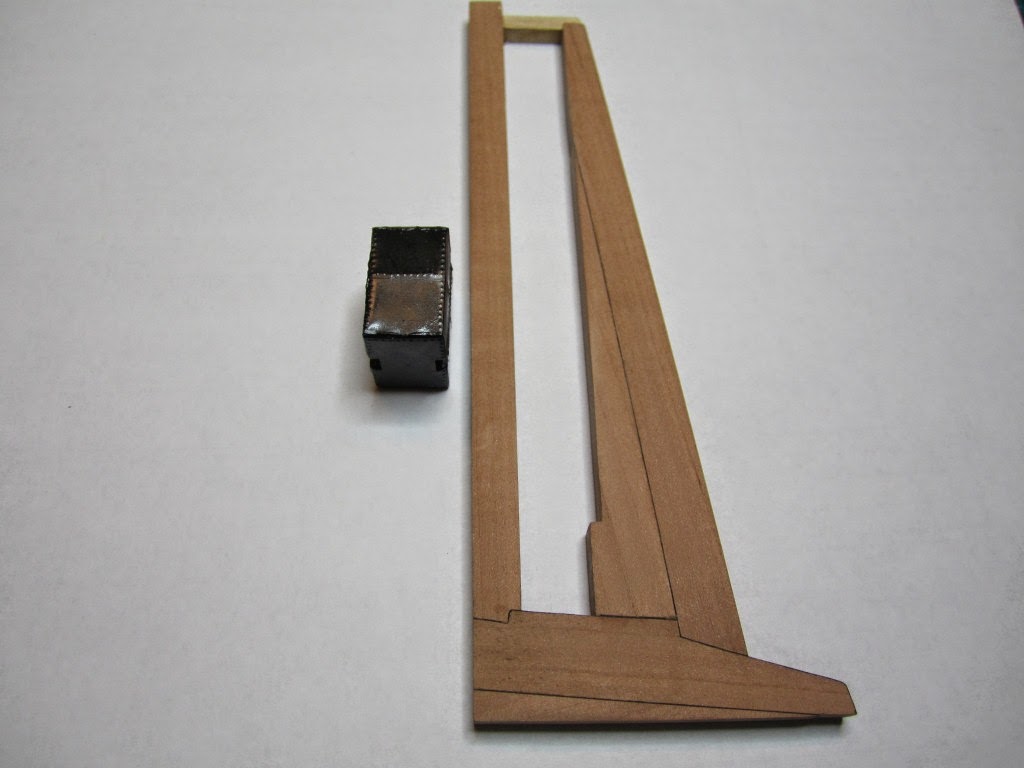
The  tank seated on the propeller rails. When the rails are glued in place on the stern the tank can be placed in the well or on deck depending on how the model will be displayed (e.g. with propeller in place or not). 


A crude model of Captain Crozier provides a sense of scale.  

Friday, 16 May 2014

ON RAILS: RAISING AND LOWERING TERROR’S SCREW

Oliver Lang's 1845 stern redesign, showcasing the propeller and rail system. 

On ships like HMS Rattler (launched two years prior to the Franklin Expedition) unshipping the propeller involved a difficult operation involving tackle over the side of the vessel. A significant advancement of HMS Terror and Erebus was a new well system used to raise and lower the propeller directly through the stern of the vessels. The well system was so novel and efficient that a demonstration comparing the unshipping procedures of the Rattler and Erebus was conducted for the Lords of the Admiralty and ­the press prior to the departure of the vessels (Anonymous 1845:279). The system was subsequently adopted on all screw powered vessels in the Royal Navy of the era.
      A significant trait of the new propeller well system was a pair of grooves or rails on the fore and aft sides of the rudderpost and sternpost, respectively. These grooves were used to guide the propeller as it was raised and lowered and to seat it firmly while it was in use. On most ships, these grooves were cut into the wood of the sternpost and rudderpost, but Oliver Lang’s design for HMS Erebus and Terror needed to be different. In his design the grooves were cut into rails which projected into the well and performed two functions:  1) the rails guided and seated the propeller when it was in use and 2) they secured the filling chocks that were to be used to strengthen the stern when the propeller wasn’t shipped.
                Unlike many Royal Navy vessels of the era, the 1845 stern plans for the ships show that rails were straight-sided, presumably because they needed to be smooth for the filling chocks to slide along their length (most rail systems of the era bulged laterally at the position where the propeller was seated). Details of the interior of these rails are not shown on the plans, but we can assume that they included a semi-circular seat for the propeller, similar to other rail systems of the era (see here and here). The fore rail would have included an aperture for the propeller shaft, which likely telescoped through this opening to fit in the hub of the propeller (Battersby and Carney 2011:206). The rails needed to be extremely robust to take pressure from pack ice; so they were likely over-fastened – on my version I included bolts at roughly the same interval as those used on Terror’s iron staple knee. The 1845 plans reveal that the rails were made from gunmetal or a similar alloy, but given the ice abuse they would need to withstand, I believe the bolts used to secure them may have been made from iron.    

References:
Anonymous,
1845    The Arctic Expedition. Literary Gazette: Journal of the Belles Lettres, Arts, Science, &c. for the Year 1845. Pp. 279. Robson, Levey, and Franklyn, London.

Battersby, William, and Carney, Peter

2011    Equipping HM Ships Erebus and Terror, 1845. International Journal for the History of Engineering  & Technology 81(2):192-211.


Sectional Plans for HMS Terror's Auxiliary Propeller System. 


I used brass tube stock with an interior diameter slightly larger than the propeller hub to make the rails. 


Tube stock cut in half and filed to the correct dimensions. 


Cutting inserts for the heel of the rails. The seat for the propeller can be seen on the left. 


Parts before soldering. 


The rails after soldering and cleanup. The scribe lines mark the position of the  bolt holes. 


The finished drilled pieces after polishing. The aperture for the telescoping coupling can be seen on the right. 


Test fit of the propeller. 


Another angle.


Dry fit of the fore rail. 


Dry fit of the propeller and rails in proper position. I admit I like the contrast between the brass and Swiss pear. 


View looking forward. The scribe lines in the rudderpost mark where the rudder groove will be cut. 


Port view. 


Again, just a dry fit prior to final assembly and finishing. 

Wednesday, 30 April 2014

HMS TERROR’S SCREW PROPELLER

Having completed the Royal Navy’s last great journey of exploration under sail power, HMS Terror’s next commission was destined to be the first major voyage of discovery to use auxiliary screw propulsion.  

The 1845 stern plans show that Oliver Lang chose a two-bladed Smith type propeller for the voyage (Battersby and Carney 2011:204). This choice makes perfect sense; in January of 1845 the Admiralty had just concluded extensive tests of screw propellers on HMS Rattler, finally settling on a two-bladed design by Smith (Carlton 2012:6; see also Bourne 1855:136).The propeller was likely made of gunmetal, similar to those used in subsequent Franklin search vessels (Dickens 1850:8) and other Royal Navy ships of the era. According to Lang’s plans, the screw was ca. 6 feet 11 inches in diameter (from tip to tip). HMS Erebus and Terror also carried a spare four-bladed propeller of the Woodcroft type (Battersby and Carney 2011:204). Roughly the same diameter as the Smith propeller, its shape and size would have necessitated that it be unshipped over the side of the vessel rather than through the propeller well.

Plans for HMS Terror's propeller. The filling chocks used when the
propeller was unshipped are on the right. 

Following others (Battersby and Carney 2011:204), I originally believed that the propeller was set in a frame that would sit flush inside the fore and aft rails/grooves in the propeller well (the rail system will be described in my next post). This was a prudent assumption, as a frame-mounted propeller was standard in screw-assisted vessels of the Royal Navy in the latter half of the 19th century. The frame was an important feature because it was used to raise and lower the propeller along the rails in the well, while providing stability when it was in use.

However, despite their common use in the era, I was puzzled by the fact that no frame is visible in the 1845 stern plan. I recently purchased high resolution scans of the plan, which permitted me to read Lang’s thorough annotations.  Needless to say, the last annotation in the list, labeled “P”, describes the reason that Lang didn’t include a frame in the plan:

“P: Propeller in place with a hole in the end of the fan to take it up by and to lower it down in place when required.“

The annotation exposes the highly expedient and experimental nature of the design, which represented a great simplification of the complex propeller lifting system used for the Rattler (view it here). While very rare, the hole-in-blade lifting system was subsequently employed on RRS Discovery by Robert Falcon Scott during his 1901 Antarctic Expedition (pictures of the hole in the blade can be found here and here). In fact, RRS Discovery appears to have borrowed many design elements from the Erebus and Terror, a testament to the advanced and efficient nature of their systems.  

Because Lang’s plans don’t show precisely how the propeller articulated with the rails in the well (the rails on the plan obscure those details), I was forced to speculate that the propeller included two retaining ferrules which would both seat the propeller and guide it as it was raised and lowered into position along the rails. In modeling this, I took inspiration from the ferrules used in contemporary Admiralty models and the RSS Discovery, though I admit they are highly generalized and speculative.

References:

Battersby, William, and Carney, Peter
2011       Equipping HM Ships Erebus and Terror, 1845. International Journal for the History of Engineering & Technology 81(2):192-211.

Bourne, John
1855       A Treatise on the Screw Propeller with Various Suggestions for Improvement. Longman, Brown, Green, and Longmans, London.

Carlton, John
2012       Marine Propellers and Propulsion. Butterworth-Heinemann, Oxford.

Dickens, Charles
1850       A Visit to the Arctic Discovery Ships. Household Words: A Weekly Journal 1:8.

Propeller blades cut from brass strip stock. 


A guide for bending the blades to the proper angle.

Bending the blade by hand. 

Checking the angle. 

Blades after bending.

Rough filed to shape, with posts for attachment to the hub.  

The hub is made from brass tube stock. 

Parts prior to assembly. 

The finished propeller, including the hole in the blade. The blades were silver -soldered to the hub,
then the entire piece was sanded with 400 grit sandpaper and buffed with superfine steel wool. 

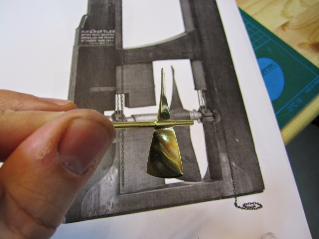
Compared to the plans. 


Assessing the profile shape. 

Comparing the prop to the model of HMS Rattler in the NMM. 

Checking fit in the well. 

Marking brass stock to fabricate the ferrules. 
Ferrules roughed out. 

Prior to final assembly. The ferrules are glued in place with metal epoxy,
rather than soldered.

The finished part - yes, it spins!