Oliver Lang's 1845 stern plans currently held in the National Maritime Museum's
collections. The title indicates that the plans are of HMS Erebus, but the dimensions
of the plan, especially the height of the bulwarks, match HMS Terror plans
more precisely. Additionally, the transcribed version of these plans occur on the
1836/37 profile plans for HMS Terror, and match the 1812 plans for Terror
relatively accurately.
In February 1845, Oliver Lang, Master Shipwright at Woolwich,
faced a daunting challenge. The Admiralty, under pressure from Parry, had
decided to outfit HMS Erebus and Terror for auxiliary screw propulsion, powered
by small passenger locomotives.
Screw propulsion was in its infancy and contemporary
designs, based on patents filed by Francis Pettit Smith and others, called for
the placement of the propeller opening in the deadwood of a steam powered vessel
(Bourne 1855:28). However, applying such a modification to polar vessels would
critically weaken the stern, and Lang knew from the Terror’s first arctic
expedition that even the most robust sternpost was severely vulnerable when
overwintering in sea ice. How could he protect the ship’s stern from the pack
when a gaping hole had to be cut in the deadwood for the propeller?
His solution appears in a plan dated March 17th, 1845, which
was subsequently transcribed onto the 1836/37 profile plan for HMS Terror.
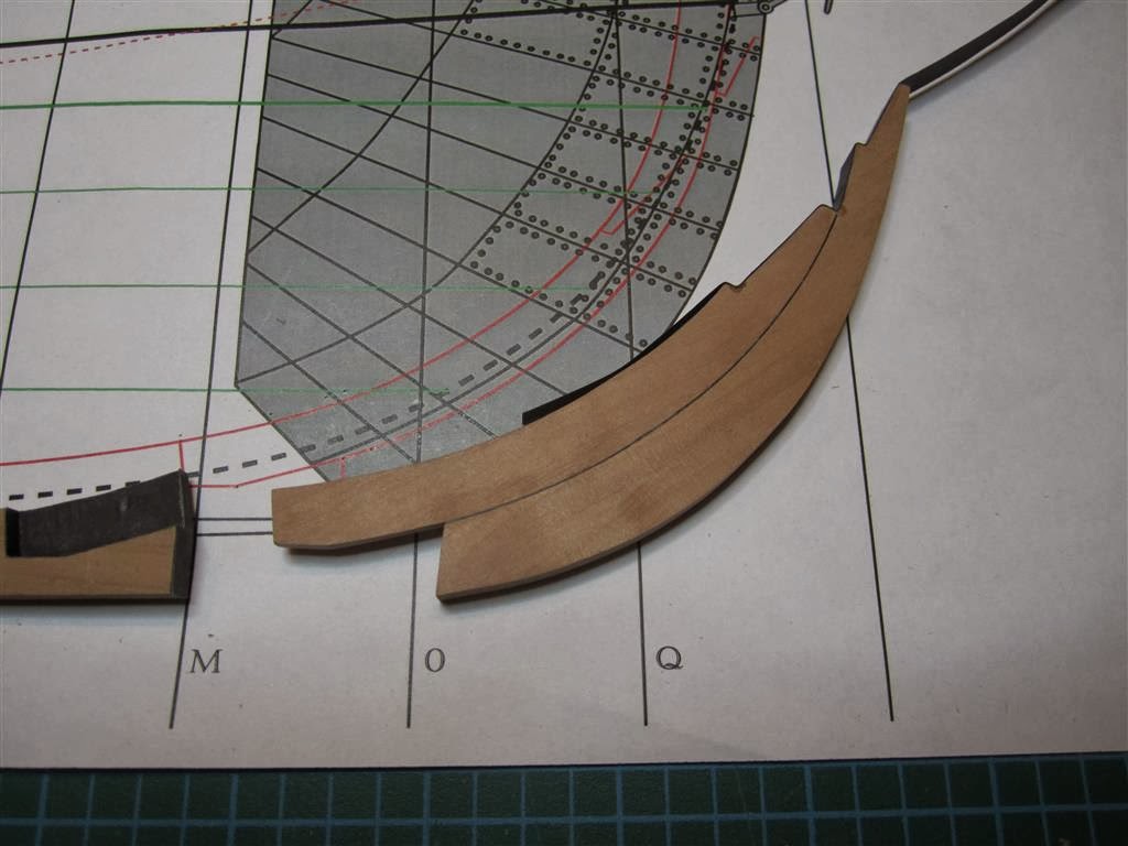
Instead of altering the ship’s existing stern, Lang simply extended the stern
of the ship aft by adding a new keel section, onto which a new rudderpost and
aperture for the propeller were attached. The 1836/37 plans seem to show that Terror’s
original sternpost had been modified for Back’s voyage, but the 1845 annotations clearly indicate that
Lang reconstructed it to the same configuration used in Terror’s original
design (alternately, it is possible that Terror’s stern was not modified in
1836 as planned).
Lang’s 1845 design called for a triangular piece of wood to be
bolted to the original sternpost, creating a vertical face for the propeller
aperture. The new rudderpost and the angled fitting were both tenoned into the
keel extension, as indicated by the presence of horizontal bolts on a
contemporarymodel of the design. The entire structure was then bolted to a massive u-shaped
“staple knee”, made from 3.5 inch thick iron, which was the same length as the propeller
opening.
Lang next turned to the problem of protecting the new
rudderpost and propeller aperture from ice damage. He settled on a well system
which could be used to ship and unship the propeller, similar to a design
patented by Joseph Taylor in 1838 (Bourne 1855:32). However, Lang’s system
included a new innovation; when the propeller was unshipped, the well would be filled
with a series of stacking wooden and steel chocks. The chocks were shaped to
match the dimensions of the new rudderpost and deadwood and would completely
fill the well, thus reinforcing the rudderpost against forces exerted by the
ice.
Taylor’s patent described that the propeller could be
shipped via “vertical grooves cut in the true and false stern posts … in which
frame the propeller is placed” (Bourne 1855:32). However, the use of reinforcing
chocks required that this system be modified. Lang replaced the grooves in the
stern and false stern with robust gunmetal rails which themselves had a vertical
slot running much of their length. The protruding rails were necessary to
secure the chocks in the propeller well and needed to be very strong to endure
the pressures of pack ice (I’ll present more on the configuration of this rail
system and the propeller in a subsequent post).
While we may
never know how Lang’s chock system faired after two years in the grinding pack
off King William Island, we can surmise that it must have worked relatively
well because the Terror survived its first winter at Beechey Island in sailing
condition. Further, we know that the same chock system was installed on the
Intrepid and Pioneer (Anonymous 1850:8), steam tenders used in the Franklin
search effort, and that both ships survived multiple winters in sea ice before
being abandoned in relatively seaworthy condition.
Scantlings for Terror’s Sternpost and
Rudderpost
Sternpost
Sided:
At Head = 13 and ½
inches
At Heel = 10 and ¾
inches
Moulded depth = 17 and ½ inches
Rudderpost
Sided:
At Head = 13 and ½ inches
At Heel = 10 and ¾
inches
Moulded depth = 13 and ½ inches
References:
Anonymous
1850 Naval Intelligence — The Arctic Expedition. The
Times. Monday , 6th
May, pg 8.
Bourne, John
1855 A
Treatise on the Screw Propeller with Various Suggestions for Improvement.
Longman, Brown, Green, and Longmans, London.
.JPG)


.JPG)


