Much of a wooden ship’s strength comes from its planking,
which provides longitudinal stiffness while unifying the frame both outboard and inboard. It is no surprise, then, that special attention was paid to HMS
Terror’s planking; originally, to
protect her from the recoil of her massive mortars within, and later to protect
her from the immense force of polar ice without. These combined pressures
resulted in the construction of perhaps the toughest wooden sailing vessel the
world has ever seen. She was, in her way, the pinnacle of the wooden
shipwright’s art - embodied in a squat, slab-sided bomb, with the lines
and dull sailing qualities of a merchantman. How can you not love HMS Terror?
 |
| My reconstruction of Terror's 1845 planking plan. |
As a bomb vessel which needed to endure the punishing impact of her mortars, a concern for increased strength was apparent in Terror’s original planking plan. The dockyard contract for her sister ship, HMS Beelzebub (1), reveals that she was originally clad in four-inch thick oak planks, exceptional for a ship of her tonnage. English oak was used for planking her weatherworks (above the waterline) while English or Dantzic (Polish) oak was used below the waterline. Terror’s original wales were five and one-half inches thick, wrought “hook and butt” fashion, which is an interlocking design common only on warships (and bombs in particular) which greatly increased the strength of her hull. I initially believed that the second layer of planking would be wrought hook and butt fashion as well, but pictures released by Parks Canada of Erebus, and detailed images of Terror painted by Owen Stanley in 1836-1837, show that top and butt planking was employed on the second layer. How many strakes were wrought in this fashion hasn’t been reported by the archaeologists, but the very detailed paintings of Terror by Owen Stanley show two normal thick strakes below the chocks and the strakes below that wrought top and butt. This is the configuration I opted to replicate on my model.
The refit of HMS Terror
for polar duty in 1835 followed a reinforcement plan that had been
well-established from the time of William Edward Parry. Like HMS Fury and Hecla, Terror’s forecastle
and quarter deck were joined to form a continuous upper deck, thereby greatly
increasing the enclosed space below. Some minor improvements to this planking
system (described in Part 2) were applied to Terror (and then Erebus)
for James Clark Ross’ Antarctic expedition in 1839. These modifications were carefully
described by Rice, the master shipwright who outfitted both ships for the Antarctic
(2):
” the side is doubled with six-inch oak plank under the
channel, increasing to eight-inch at the wale, which is three feet broad; from
thence, through a space of five feet, the doubling diminishes to three inches
in thickness, of English elm, and the remainder of the bottom to the keel is
doubled with three-inch Canada elm….”
 |
| Midship Section Plan for Erebus and Terror. National Maritime Museum, ZAZ5678 Copyright: CC BY-NC-SA |
Beelzebub’s contract (1) indicates that Terror was planked with a three-plank shift (meaning that on each frame, three planks occurred between each plank butt, or plank end), which appears to have also been used on the subsequent second layer of planking (at least on Erebus). We don’t know how many strakes were used on Terror’s hull, but the 1839 Erebus cross section plan (3) indicates that 34 strakes (plus the garboard strake) were used on both the outer and inner layers below the chock channels.
Lang’s 1845 stern modification plan (4) provides crucial
details on the planking configuration used for the modified stern. In addition
to the general planking run, it reveals that the hull planks averaged between
9.5 and 10 inches in width, and that the garboard strake was unusually broad,
about twice the width of the bottom planks. Because of the extra-wide garboard
strake, and the smaller overall dimensions of Terror, I estimated that Terror
was planked with 30 strakes plus the wide garboard (assuming each strake was 9.5
to 10 inches in width).
I made two fundamental mistakes when planning to plank Terror’s hull in 2013. The first of these was deciding to double-plank her hull, just like the real ship. I began planking my model in the fall of 2016. In a previous blog post, I showed how I planked Terror’s topside weatherworks above the chocks. I followed a similar methodology for the hull, but rather than edge-bending planks, I had to carefully spile them (a technique used by actual shipwrights to calculate, then cut, the precise curve and run of a plank), as this was necessary to plank the bluffer parts of Terror’s bow.
Spiling greatly slowed my progress, and I was only able to complete one or two strakes in an evening. With 120 strakes necessary for both layers of hull planking, not including the ice chocks, stern, and upper deck, I rapidly realized that I was facing a crisis. The deadline to deliver my model for the Death in the Ice exhibition was in June of 2017, and it quickly became apparent that I would not make that deadline if I did not increase my output. Thus, I began the great planking of 2017.
 |
| 1845 Stern Profile form Erebus and Terror. Note the planking detail. National Maritime Museum, ZAZ5683 Copyright: CC BY-NC-SA |
I made two fundamental mistakes when planning to plank Terror’s hull in 2013. The first of these was deciding to double-plank her hull, just like the real ship. I began planking my model in the fall of 2016. In a previous blog post, I showed how I planked Terror’s topside weatherworks above the chocks. I followed a similar methodology for the hull, but rather than edge-bending planks, I had to carefully spile them (a technique used by actual shipwrights to calculate, then cut, the precise curve and run of a plank), as this was necessary to plank the bluffer parts of Terror’s bow.
 |
| The first strake added to the hull. For fellow ship modelers: the white line was my first inadequate attempt to line off the bottom of the wales. I fixed the run shortly after this picture was taken. |
 |
| The first strake at the bow. This image reveals how bluff Terror was just above the waterline. Again, this was taken before I adjusted the reference line on the hull. |
Spiling greatly slowed my progress, and I was only able to complete one or two strakes in an evening. With 120 strakes necessary for both layers of hull planking, not including the ice chocks, stern, and upper deck, I rapidly realized that I was facing a crisis. The deadline to deliver my model for the Death in the Ice exhibition was in June of 2017, and it quickly became apparent that I would not make that deadline if I did not increase my output. Thus, I began the great planking of 2017.
It began with a compromise. To speed up the first layer of
planking, I decided to double the width of each of the lower hull strakes and
to not follow the stated plank shift pattern (which requires more cutting).
While this layer will never be visible, I regret not having completed it to
scale; in addition, not having a photograph of Terror’s original planking configuration remains a sincere source of
dissatisfaction for me.
My second mistake was to plank the second layer of my model using
accurate scale plank thicknesses. Some of the planks on Terror’s wales are 8 inches thick, representing a daunting task at
1:48th scale. While the three and four-inch scale planks could easily be bent
with a crimping tool and some heat from a blow dryer, this technique simply
would not work on planks thicker than five scale inches. Every thick plank had
to be soaked in near-boiling water for 20 minutes, carefully crimped with a
plank bender, and then pressed into shape using a bending iron and a curved
jig. On top of that, each plank had to be carefully spiled before bending, and
the distortion caused by swelling wood and heat treatment caused no end of
difficulty. An added complication was that the thickest strakes, at the wales,
had to be laid top and butt fashion, which further complicated the spiling
process.
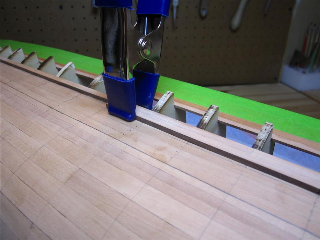 |
| The second layer of planking in progress. You can see here where I made the decision to widen each strake on the first layer (about January 2017). |
 |
Detail showing the transition to 8" strakes at wales. The upper two 8" stakes were sanded
to provide a smooth run to the 6" planks above them. |
 |
| The third strake of 8" top and butt planking at the bow.Notice the drop strake below it in the first layer of planking. |
 |
| Top and butt planking in progress. The tape protects the wood at the stern and bow during planking. |
 |
| Detail of the completed top and butt planking. |
 |
| Adding the absurdly wide garboard strake on the second layer. |
 |
| Close up of the garboard strake at midships. According to contemporary plans, the garboard strake of the second layer was not rabbeted into the keel. Interestingly, it was on later polar vessels, like HMS Investigator. |
 |
| The final garboard planks at the stern, after bending them into shape. |
 |
| Bottom planking in progress. This photo shows how I lined off the second layer of planking. |
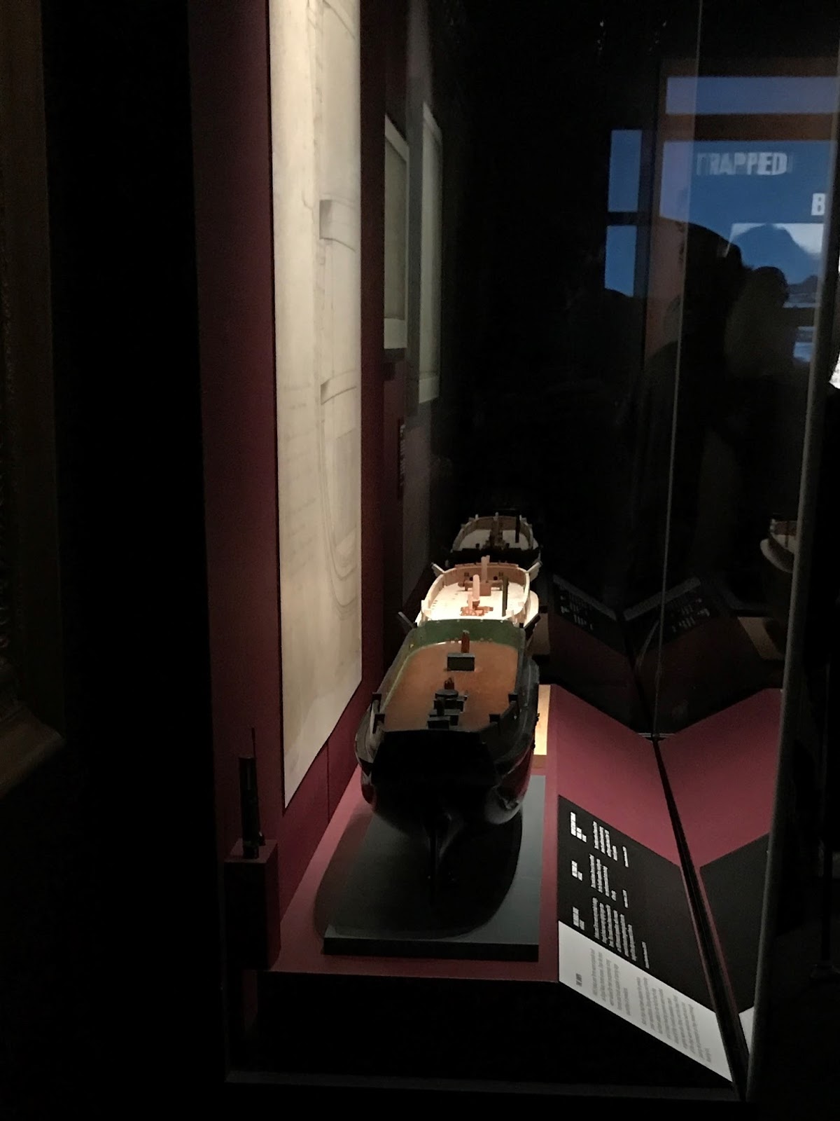
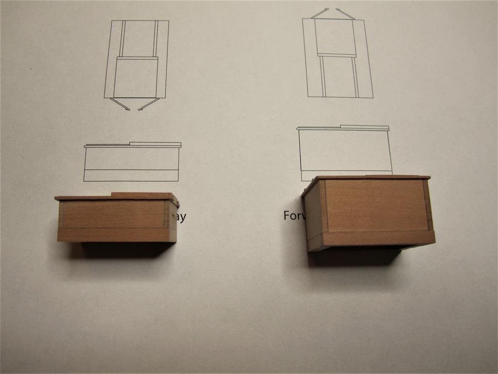
The most difficult part of the hull planking occurred with the stern. The first layer of planking was relatively simple as it abutted the rabbet on the original stern post (hence this layer was planked like every other ship). However, Lang’s conversion of Erebus and Terror to steam locomotion required that the second layer of planking form the walls of the propeller well (4). This meant that the second layer extended over the original stern post and propeller well and was rabbeted into the new rudder post. I’ve known for some time what shape this configuration would take, but implementing it required a lot of trial and error, despite Lang’s detailed plans and a block model (5) for guidance. The most difficult chore was bending and spilling the planks into the proper shape, especially the strake forming the lower margin of the well. It also required the use of two “stealers” to accommodate the increased area of the stern. However, once installed, I’m convinced the model respects Lang’s design, the 1845 block model, and the practical reality faced by the shipwrights who had to plank this unusual ship.
 |
| I use masking tape to make spiling templates. This shows the extreme shape of the first stern plank above the propeller opening at the stern. Lang didn't make the shipwright's task easy! |
 |
| The resulting pearwood plank. |
 |
| To achieve the complex bend in the plank, I soaked it in hot water, then clamped it in place until it dried. |
 |
| One of the stealer planks in the stern, after it had been bent to shape. |
 |
| Terror's unusual stern, prior to sanding and finish. Oliver Lang designed only one stealer in this area , but I found it impossible to plank without a second. I'll discuss the planking of the transom and chock channel in Part 2. |
 |
| The completed second layer at the bow. Note the drop planks below the wales. On the finished model this is completely covered by a third layer of wood and "iron" plating. I didn't need to spend such care at the bow, but a modeler can only accept so much compromise. I'll discuss the planking of the chock channel "ice bumper" in Part 2. |
 |
| The completed planking prior to sanding, bow plating, and finish. I'll discuss the planking of the chock channel "ice bumper" in Part 2 |
Part 2 of my post details the planking of Terror’s chock channels (or “ice bumper”), her transom, and her upper deck. Stay tuned!
--------------------
Footnotes:
(1) National Maritime Museum, ADT0010
(2)Ross,
Sir James Clark, 1847. A Voyage of Discovery
and Research in the Southern and Antarctic Regions, During the Years 1839-1843:
Volume I. John Murray, London.
(3)National Maritime Museum, ZAZ5678
(4)National Maritime Museum, ZAZ5683
(5)National Maritime Museum, SLR2253


