Having completed the Royal Navy’s last great journey of exploration
under sail power, HMS Terror’s next commission was destined to be the first
major voyage of discovery to use auxiliary screw propulsion.
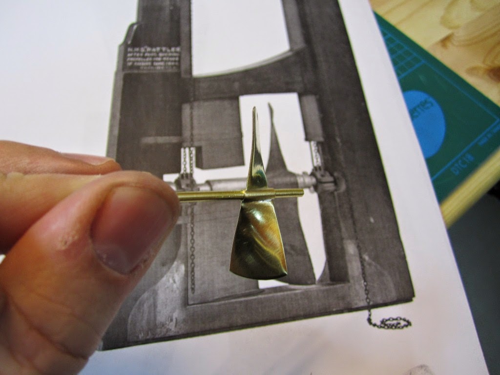
The 1845 stern plans show that Oliver Lang chose a two-bladed Smith
type propeller for the voyage (Battersby and Carney 2011:204). This choice
makes perfect sense; in January of 1845 the Admiralty had just concluded
extensive tests of screw propellers on HMS Rattler, finally settling on a
two-bladed design by Smith (Carlton 2012:6; see also Bourne 1855:136).The propeller was likely made of
gunmetal, similar to those used in subsequent Franklin search vessels (Dickens
1850:8) and other Royal Navy ships of the era. According to Lang’s plans, the screw
was ca. 6 feet 11 inches in diameter (from tip to tip). HMS Erebus and Terror also
carried a spare four-bladed propeller of the Woodcroft type (Battersby and
Carney 2011:204). Roughly the same diameter as the Smith propeller, its shape and
size would have necessitated that it be unshipped over the side of the vessel
rather than through the propeller well.
 |
Plans for HMS Terror's propeller. The filling chocks used when the
propeller was unshipped are on the right. |
Following others (Battersby and Carney
2011:204), I originally believed that the propeller was set
in a frame that would sit flush inside the fore and aft rails/grooves in
the propeller well (the rail system will be described in my next post). This
was a prudent assumption, as a frame-mounted propeller was standard in screw-assisted
vessels of the Royal Navy in the latter half of the 19th century.
The frame was an important feature because it was used to raise and lower the
propeller along the rails in the well, while providing stability when it was
in use.
However, despite their common use in the
era, I was puzzled by the fact that no frame is visible in the 1845 stern plan.
I recently purchased high resolution scans of the plan, which permitted me to
read Lang’s thorough annotations. Needless
to say, the last annotation in the list, labeled “P”, describes the reason that
Lang didn’t include a frame in the plan:
“P: Propeller in place with a hole in the
end of the fan to take it up by and to lower it down in place when required.“
The annotation exposes the highly expedient
and experimental nature of the design, which represented a great simplification
of the complex propeller lifting system used for the Rattler (view it here).
While very rare, the hole-in-blade lifting system was subsequently employed on RRS Discovery by Robert Falcon Scott during his 1901 Antarctic Expedition (pictures
of the hole in the blade can be found here
and here).
In fact, RRS Discovery appears to have borrowed many design elements from
the Erebus and Terror, a testament to the advanced and efficient nature of
their systems.
Because Lang’s plans don’t show precisely
how the propeller articulated with the rails in the well (the rails on the plan
obscure those details), I was forced to speculate that the propeller included
two retaining ferrules which would both seat the propeller and guide it as it
was raised and lowered into position along the rails. In modeling this, I took
inspiration from the ferrules used in contemporary
Admiralty models and the RSS
Discovery, though I admit they are highly generalized and speculative.
References:
Battersby, William, and Carney, Peter
2011 Equipping HM Ships Erebus
and Terror, 1845. International Journal
for the History of Engineering &
Technology 81(2):192-211.
Bourne, John
1855 A Treatise on the Screw Propeller with
Various Suggestions for Improvement. Longman, Brown, Green, and Longmans,
London.
Carlton, John
2012 Marine Propellers and Propulsion. Butterworth-Heinemann,
Oxford.
Dickens, Charles