“Fairing” is an important step in constructing an
accurate hull shape on a ship model. It involves sanding and beveling the
bulkheads to create an even surface for the planking to sit flat against the
hull frame.
For my build, this was an extended process that allowed me
to learn much about the construction of Terror
and Erebus, especially at the stern and the bow.
In this post, I will present a photo essay documenting the steps I took to prepare the hull for planking. As I progress through the steps, I'll discuss what I learned about Franklin’s exploration vessels.
 |
| Before I could begin faring the hull, it was necessary to fill in the stern and bow of the model using filling blocks. I created these from 1/4" plywood, laser cut using measurements from the ship's plans. This image displays the three starboard filling blocks used at the bow. |
 |
| The filling blocks were carved to shape using card guides cut to match the lines of the half breadth plan. |
 |
| Placing the filling blocks side-by-side as they were carved ensured that they were symmetrical. The lamination in the plywood was also helpful in this regard. However, plywood is a poor carving material, and I would think twice about using it again. |
 |
| In 1839, the solid chock (ice) channels on Terror were extended around the bow. I constructed these from several layers of basswood. |
 | |
|
 |
| The ice channels were glued in place on the bow and scrap wood was used to rough out the bulwark shape. The excessive use of glue didn't escape Mini-Crozier's critical eye. |
 |
| The gaps in the bulwarks were filled using basswood strips of appropriate thickness. |
 |
| Rather than filling and sanding seams and gaps, basswood leveling strips were applied to the upper surface of the ice channels. The channels were then filed to shape using card stock templates. Scrap wood was used to fill in any large gaps in the bulwarks. |
 |
| The completed bow just prior to sanding. I checked the symmetry and level of each side of the ice channel obsessively with a height gauge while the model was still on its building board. The asymmetry of the filling stock used to shape the bulwarks is a product of the odds and ends in my spoil bin, and while unsightly, it won't be visible when the model is planked. |
 |
| This image shows the faired forward bulkheads and bow filling blocks, just prior to final sanding. The merchant-like shape of Terror's bow and the imposing nature of the ice channel grafted to it can be seen in this view. Note how far the ice channel overhangs the bow relative to the port side of the ship; this is because it sits on three layers of planking, including a layer of 3" lower planks, a second layer of 8" planks, and a third layer of even thicker reinforcing planks. |
 |
| An image of the faired stern, detailing the single filling block used in this area. The stern rabbet is in the process of being finalized in this image. |
 |
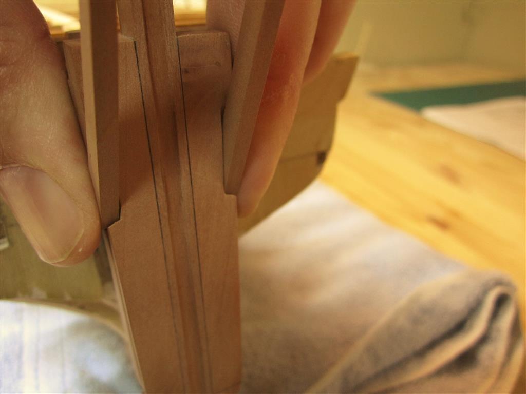
| With the hull faired, the stern timbers could be installed. These were laser cut from Swiss pear. The outermost stern timbers, on the left, were cut in two sections, as they form an angle when installed correctly. |
Prior to describing how the stern timbers were installed, it is important to note how this area of the ship was designed by Oliver Lang, the shipwright who refit Erebus and Terror for the Franklin Expedition. Because of the massive size of the propeller well and the rudder post which formed its aft wall, Lang had little room left to fit the six stern timbers and four stern lights (windows) in the counter. His solution can be seen in the 1845 Erebus and Terror stern model in the collection of the National Maritime Museum, in Chatham.
Inspection of the propeller well in that model shows that the stern timbers were actually used to form side walls of the well. However, they could not be fayed directly to the sides of the rudder post as this wouldn't leave enough space for the stern lights (windows). This meant that the stern timbers had to be inset into the sides of the rudder post by three inches to form the side walls of the propeller well. Remarkably, Lang achieved all of this with almost no modification of Terror's existing stern framing. With the rudder post locked directly into the two central stern timbers, the whole structure was incredibly robust. It is important to note that the inset stern timbers may not have been needed on Erebus, which had a slightly wider counter than Terror.
 |
| Simplified plan of Terror's counter architecture. Note how the stern timbers overlap the rudder post. Also noteworthy is the position of the upper deck transom, which could be fayed directly to the aft side of the rudder post in this configuration. |
 |
| In this image, the slot/inset for the stern timber has been cut into the rudder post. Note how it is level with the interior sides of the propeller well. |
 |
| A view from the aft side of the rudder post showing the insets for the stern timbers. Note the square slots in the stern filling blocks cut to accept the heels of the stern timbers (no wing transom was required for construction for this stage). |
 |
| Checking the fit with a stern timber. This won't be visible in the finished model. |
 |
| Checking alignment. |
 |
| The stern timbers were fitted with the help of a jig. The jig was designed to be clamped to the bulwarks, using the station lines printed on it as guides. |
 |
| Detail of the aft part of the jig. |
 |
| A height gauge was necessary to ensure that the jig was properly aligned along its aft margin. This gauge slid tightly over the aft support of the building board, using the tracks on the left. |
 |
| The jig and height gauge in place, with the center two stern timbers installed and clamped. |
 |
| "Wing transom" filling pieces. These are not entirely accurate architecturally (they are more like half-transoms), but were carved and sanded to shape to provide a platform for planking the stern. |
 |
| The "wing transom" in place. Note the very slight curve in the transom. As confirmed by the 1845 stern model and the 1839 model of Erebus, Terror's stern was very square indeed. |
 |
| Rough transverse framing was installed to support the stern timbers. This framing is not accurate to plan or scale but rather simply supports the structure and will not be visible when the model is planked. See the above plan for the correct framing. As with the bow, I obsessively relied on a height gauge to ensure the entire structure was level and square. |
 |
| A port side view, detailing the stern architecture. Note how the stern timbers adjoined the propeller well and rudder post. |
 |
| The completed stern. |
Completing the construction and fairing of the model's stern was a milestone for my project. Not only is the model now ready for planking, finishing this stage of the build revealed a minor mystery surrounding how Lang planked Terror's stern . Lang's 1845 stern refit plan stated that an "....additional part of the wale [was] added to the after end of the ship to form the well or trunk..." for the propeller. Unfortunately, his plan does not reveal if both layers of planking were extended to accomplish this (Terror was double planked against the ice). However, with the construction of this part of the model, his solution became clear to me.
If my model is correct, then it shows that the first layer of Terror's hull planking did not need to be modified in any way by Lang. In fact, it could simply be left in place, terminating at the edge of the lower counter, as was typical of bomb vessels. Again, if my model architecture is correct, then it shows that Lang could have just extended the second layer of planking to the rudder post. The 1845 stern model shows that this planking rose straight up the rudder post and, when it hit the counter, turned to trace a graceful arc, running from the upper end of the stern rabbet to the lowest portion of the counter at the sides (these planks were fayed directly to the previously planked counter). Lang's stern plan shows that the second layer abutted a beveled margin plank on the counter, although this isn't detailed on his stern model.
 |
| My planking plan for Terror's stern. The red lines show the lower planking, while the white lines show the upper level of planking. The overlap of the planks accords well with the 1839 midships section for Erebus and Terror. |
 |
| The current condition of Terror. She's just about ready for planking. |
 |
| A view from the upper deck. |