Friday, 16 May 2014

ON RAILS: RAISING AND LOWERING TERROR’S SCREW

Oliver Lang's 1845 stern redesign, showcasing the propeller and rail system. 

On ships like HMS Rattler (launched two years prior to the Franklin Expedition) unshipping the propeller involved a difficult operation involving tackle over the side of the vessel. A significant advancement of HMS Terror and Erebus was a new well system used to raise and lower the propeller directly through the stern of the vessels. The well system was so novel and efficient that a demonstration comparing the unshipping procedures of the Rattler and Erebus was conducted for the Lords of the Admiralty and ­the press prior to the departure of the vessels (Anonymous 1845:279). The system was subsequently adopted on all screw powered vessels in the Royal Navy of the era.
      A significant trait of the new propeller well system was a pair of grooves or rails on the fore and aft sides of the rudderpost and sternpost, respectively. These grooves were used to guide the propeller as it was raised and lowered and to seat it firmly while it was in use. On most ships, these grooves were cut into the wood of the sternpost and rudderpost, but Oliver Lang’s design for HMS Erebus and Terror needed to be different. In his design the grooves were cut into rails which projected into the well and performed two functions:  1) the rails guided and seated the propeller when it was in use and 2) they secured the filling chocks that were to be used to strengthen the stern when the propeller wasn’t shipped.
                Unlike many Royal Navy vessels of the era, the 1845 stern plans for the ships show that rails were straight-sided, presumably because they needed to be smooth for the filling chocks to slide along their length (most rail systems of the era bulged laterally at the position where the propeller was seated). Details of the interior of these rails are not shown on the plans, but we can assume that they included a semi-circular seat for the propeller, similar to other rail systems of the era (see here and here). The fore rail would have included an aperture for the propeller shaft, which likely telescoped through this opening to fit in the hub of the propeller (Battersby and Carney 2011:206). The rails needed to be extremely robust to take pressure from pack ice; so they were likely over-fastened – on my version I included bolts at roughly the same interval as those used on Terror’s iron staple knee. The 1845 plans reveal that the rails were made from gunmetal or a similar alloy, but given the ice abuse they would need to withstand, I believe the bolts used to secure them may have been made from iron.    

References:
Anonymous,
1845    The Arctic Expedition. Literary Gazette: Journal of the Belles Lettres, Arts, Science, &c. for the Year 1845. Pp. 279. Robson, Levey, and Franklyn, London.

Battersby, William, and Carney, Peter

2011    Equipping HM Ships Erebus and Terror, 1845. International Journal for the History of Engineering  & Technology 81(2):192-211.


Sectional Plans for HMS Terror's Auxiliary Propeller System. 


I used brass tube stock with an interior diameter slightly larger than the propeller hub to make the rails. 


Tube stock cut in half and filed to the correct dimensions. 


Cutting inserts for the heel of the rails. The seat for the propeller can be seen on the left. 


Parts before soldering. 


The rails after soldering and cleanup. The scribe lines mark the position of the  bolt holes. 


The finished drilled pieces after polishing. The aperture for the telescoping coupling can be seen on the right. 


Test fit of the propeller. 


Another angle.


Dry fit of the fore rail. 


Dry fit of the propeller and rails in proper position. I admit I like the contrast between the brass and Swiss pear. 


View looking forward. The scribe lines in the rudderpost mark where the rudder groove will be cut. 


Port view. 


Again, just a dry fit prior to final assembly and finishing. 

Wednesday, 30 April 2014

HMS TERROR’S SCREW PROPELLER

Having completed the Royal Navy’s last great journey of exploration under sail power, HMS Terror’s next commission was destined to be the first major voyage of discovery to use auxiliary screw propulsion.  

The 1845 stern plans show that Oliver Lang chose a two-bladed Smith type propeller for the voyage (Battersby and Carney 2011:204). This choice makes perfect sense; in January of 1845 the Admiralty had just concluded extensive tests of screw propellers on HMS Rattler, finally settling on a two-bladed design by Smith (Carlton 2012:6; see also Bourne 1855:136).The propeller was likely made of gunmetal, similar to those used in subsequent Franklin search vessels (Dickens 1850:8) and other Royal Navy ships of the era. According to Lang’s plans, the screw was ca. 6 feet 11 inches in diameter (from tip to tip). HMS Erebus and Terror also carried a spare four-bladed propeller of the Woodcroft type (Battersby and Carney 2011:204). Roughly the same diameter as the Smith propeller, its shape and size would have necessitated that it be unshipped over the side of the vessel rather than through the propeller well.

Plans for HMS Terror's propeller. The filling chocks used when the
propeller was unshipped are on the right. 

Following others (Battersby and Carney 2011:204), I originally believed that the propeller was set in a frame that would sit flush inside the fore and aft rails/grooves in the propeller well (the rail system will be described in my next post). This was a prudent assumption, as a frame-mounted propeller was standard in screw-assisted vessels of the Royal Navy in the latter half of the 19th century. The frame was an important feature because it was used to raise and lower the propeller along the rails in the well, while providing stability when it was in use.

However, despite their common use in the era, I was puzzled by the fact that no frame is visible in the 1845 stern plan. I recently purchased high resolution scans of the plan, which permitted me to read Lang’s thorough annotations.  Needless to say, the last annotation in the list, labeled “P”, describes the reason that Lang didn’t include a frame in the plan:

“P: Propeller in place with a hole in the end of the fan to take it up by and to lower it down in place when required.“

The annotation exposes the highly expedient and experimental nature of the design, which represented a great simplification of the complex propeller lifting system used for the Rattler (view it here). While very rare, the hole-in-blade lifting system was subsequently employed on RRS Discovery by Robert Falcon Scott during his 1901 Antarctic Expedition (pictures of the hole in the blade can be found here and here). In fact, RRS Discovery appears to have borrowed many design elements from the Erebus and Terror, a testament to the advanced and efficient nature of their systems.  

Because Lang’s plans don’t show precisely how the propeller articulated with the rails in the well (the rails on the plan obscure those details), I was forced to speculate that the propeller included two retaining ferrules which would both seat the propeller and guide it as it was raised and lowered into position along the rails. In modeling this, I took inspiration from the ferrules used in contemporary Admiralty models and the RSS Discovery, though I admit they are highly generalized and speculative.

References:

Battersby, William, and Carney, Peter
2011       Equipping HM Ships Erebus and Terror, 1845. International Journal for the History of Engineering & Technology 81(2):192-211.

Bourne, John
1855       A Treatise on the Screw Propeller with Various Suggestions for Improvement. Longman, Brown, Green, and Longmans, London.

Carlton, John
2012       Marine Propellers and Propulsion. Butterworth-Heinemann, Oxford.

Dickens, Charles
1850       A Visit to the Arctic Discovery Ships. Household Words: A Weekly Journal 1:8.

Propeller blades cut from brass strip stock. 


A guide for bending the blades to the proper angle.

Bending the blade by hand. 

Checking the angle. 

Blades after bending.

Rough filed to shape, with posts for attachment to the hub.  

The hub is made from brass tube stock. 

Parts prior to assembly. 

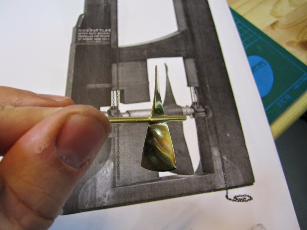
The finished propeller, including the hole in the blade. The blades were silver -soldered to the hub,
then the entire piece was sanded with 400 grit sandpaper and buffed with superfine steel wool. 

Compared to the plans. 


Assessing the profile shape. 

Comparing the prop to the model of HMS Rattler in the NMM. 

Checking fit in the well. 

Marking brass stock to fabricate the ferrules. 
Ferrules roughed out. 

Prior to final assembly. The ferrules are glued in place with metal epoxy,
rather than soldered.

The finished part - yes, it spins!

Wednesday, 2 April 2014

IRON WORK

Oliver Lang's 1845 stern redesign. Note the iron strapping. 

Oliver Lang’s 1845 modifications to Terror’s stern involved a significant amount of iron reinforcement. In my last post, I documented the design of the iron staple knee, which was central to the construction of the propeller well and new rudderpost. However, Lang also added four large iron straps to reinforce the joints between the keel, the rudderpost and the sternpost. These straps were u-shaped and passed between the false keel and the keel, permitting the former to break free in the case of the stern running aground.
According to Lang’s notes, the straps appear to have been bolted entirely through the width of the stern to provide extra rigidity. This created an exceptionally strong iron-laced structure, a design which exposed Lang's worry about the ice pressure to be exerted on the Terror’s stern.

The 1845 stern modification plan reveals that the straps were 4 and 1/2 inches wide, with bolts approximately 1 and 1/8th inches in diameter. I estimate, based on bracing and strapping shown on cross section plans of HMS Erebus/Terror and HMS Investigator, that they were ca. 1 to 1.5 inches thick.


All of the parts shown below are made from larger brass strips, which were cut, filed, and drilled by hand. The bolts are made from brass straight pins; the heads were filed by hand to scale (2 inches) and soldered into place. The brass was then blackened to simulate iron. 


The foremost strap prior to adding the bolts. 

The staple knee and remaining straps with bolts soldered in place. The three aft straps would normally look similar to the one on the right, but I've decided only to model the visible portions of the straps (i.e. the portions not buried between the keel and false keel). Each is composed of two parts to be glued on opposite sides of the model. 


Detail of the newly added bolts. 


Brass parts soaking in the blackening agent. 


The finished parts.


The iron reinforcements in place (dry fit only until the propeller rails are completed).


Again, just a test to see how they will look when finally installed. 


Thursday, 27 February 2014

MODELING THE "IRON STAPLE KNEE”

In my last post, I described Oliver Lang’s unique modifications to HMS Terror’s stern to accommodate the screw propeller. A primary component of this modification was a massive 3.5 inch thick “iron staple knee”, which securely bound the keel, original sternpost, and rudderpost together.

To model this part, I will use brass, blackened to simulate iron. I originally attempted to bend and hammer a 1.85 mm thick piece of brass into the correct shape, but try as I might, I could not create the appropriate angles accurately and only produced a mangled mess. Finally, I resigned myself to the fact that I would need to cut three separate pieces and then silver solder them together. I had never attempted this before, but I found a great deal of information on Model Ship World, and decided to give it a try.  


Brass stock cut to match the dimensions of the three sides of the knee. 

Preparing to drill the holes for the bolts.

A rough jig necessary to hold the pieces in place while soldering.

The drilled pieces. 

My new pen torch and other soldering equipment.

Clamping the pieces to the jig. It was a tricky task not to burn the jig, but thankfully the joints were small and the brass heated rapidly.

The knee after soldering. The joints are much stronger than I hoped they would be.

The final part filed to shape and compared to the plans. 


An alternate view of the finished part.

The knee dry-fitted to the stern piece.