In the fall of 1825, Sir Edward Parry was court martialed at
Sheerness for the loss of one of his arctic exploration ships, HMS Fury, which he had abandoned at Somerset
Island. He and his officers were easily acquitted, but during the trial
he admitted that things might have been far worse, if not for a new piece of
equipment installed on his ships. He claimed that a new capstan, Captain
Phillips’ Patent, had saved the expedition from at least another year
trapped in ice.
Before the 19th century, capstans were largely direct drive
machinery, meaning that all of the capstan's power came from the men turning
it. However, with the introduction of geared capstans, the power of these
fittings was greatly increased. Inventors
had experimented with these “improved”, or “power”, capstans since the mid-18th
century, but poor manufacture of the gears appears to have hampered their
reliability. (1)
Charles Phillips, then a commander in the Royal Navy,
believed these powerful new capstans had the potential to revolutionize the way
ships were moved using lines and anchors (critical for saving grounded vessels).
In 1817, he submitted a plan to the Admiralty outlining a method for using them,
but without a reliable power capstan, the plan could not be implemented. In
1819, he again returned to the Admiralty, but this time with a patent for his
own improved design (Patent No. 4394).
His patent used planet gearing within an encircling gear
ring to increase the power of the capstan by a factor of three. The gears could
be rapidly engaged or disengaged using four drop pins. With the upper pins
engaged and the lower pins removed, the capstan operated in direct-drive mode.
When the lower pins were engaged and the upper pins were removed, the gear
drive was enabled and the power was increased (and the speed decreased).
It seems the Admiralty began to adopt the new design, albeit
in a limited manner, after 1819. Phillips was given a command as a result of
his invention, and he continued to command vessels while filing new patents for
nautical inventions. (1) John Richardson named an island after Phillips in 1826
and in 1829 he was nominated a Fellow of Royal Society, both largely on the
popularity of his improved capstan.
Seeing the potential for using them in ice conditions, Sir
Edward Parry installed Phillips’ Capstans on both Hecla and Fury for his third
voyage to the Arctic in 1824. He gave
the highest praise to the devices, which he used to literally haul the ships
through the ice.
Parry wrote:
“The strain we constantly had occasion to heave on the
hawsers, as springs to force the ships through the ice, was such as, perhaps,
no ships ever before attempted; and by means of Phillips's invaluable capstan
we often separated floes of such magnitude as must otherwise have baffled every
effort.” (2)
He continued, in a footnote:
“I cannot omit this opportunity of expressing my admiration
of this ingenious contrivance in every trial to which we put it in the course
of this voyage.” (3)
It seems Parry’s endorsement carried great weight with “…the
Lords of the Admiralty, who, with a laudable zeal for the service, gave
instructions that all the vessels of his Majesty's navy are in future to be
fitted out Capt. Phillips's new capstans.” (4) It is no surprise then that Phillips’
Capstans were installed in Terror and
Erebus in 1839 for Ross’ Antarctic
voyage.
The 1839 profile of Terror
and Erebus clearly shows a Phillips
style capstan installed on the upper deck, and the 1848 profile of HMS
Investigator provides a virtually identical illustration. Unfortunately, the
draughts are missing many crucial details, and therefore I was forced to conduct
further research to create accurate plans. Like nearly every part of my HMS Terror project, this proved to be far
more difficult that I originally assumed.
Because of the popularity of Phillips’ design, myriad
updated versions of these capstans were constructed over the years. Besides the
original patent drawings, several plans for different versions can be found in
the historic literature. Additionally, several demonstration models have
survived in museums, all with slightly different designs. Finally, a Phillips designed capstan still exists on HMS Unicorn (1824), and it is also slightly
different from the contemporary models and plans.
I started my reconstruction with an assumption that the basic profile, shape, and features of the capstan were accurately depicted on the 1839 profile plans (their consistency with the Investigator plans, as well as their overall accuracy, provides good support for this). Using the 1839 drawings as a base, I determined to add details from sources dated as closely as possible to 1839.
A primary source of information comes from the 1854 Encyclopaedia Britannica (5), which contains a detailed plan of a two-capstan (upper and lower deck) version of Phillips’ 1827 patent (No. 5505), specifically for Royal Navy ships. The plan differs little from Phillips’ original 1827 patent, though it shows a gear mechanism placed below the pall rim and a less robust gear plate, both common traits in later designs. Fortunately, an 1837 plan of a single capstan for a merchant vessel (recall that Terror and Erebus were based on merchant designs) exists (6), and I drew crucial information from this plan. It accords very well with the 1854 and 1827 plans, although the gear mechanism and other details would not fit the plank and beam arrangement shown on the 1839 Terror and Erebus plans. The notes accompanying the plan indicate that Royal Navy models were slightly different than this plan, and hence I believe the 1854 plans, which are consistent with the planking arrangement on Terror, are likely to be most representative of the overall gear design.
Further valuable information about the gear design and gear
plate design, as well as information on the pawl configuration and rim, comes from
contemporary models. A beautiful 1827 model single capstan exists in the
Science
Museum collection. Two additional models of the 1819 versions of Phillips’
capstan can be found in the
Rijksmuseum
in Amsterdam.
The capstan on HMS
Unicorn has been heavily modified (
the
upper even has table lamps built into it), but it provided valuable
construction information, especially on the appearance and construction of the
barrel and whelps on the upper capstan, and the gears and gear plates on the
lower capstan. Believing that additional robustness would have been necessary,
I added full thickness chocks on the upper part of the capstan to my plans and
model, matching those on HMS
Unicorn’s upper capstan. This is the only detail
of my plan not consistent with the 1839
Erebus
and
Terror sheets.
 |
An 1839 era Phillips capstan, as I believe it may have been
configured for use on HMS Erebus and Terror. |
Constructing the model of
Terror’s capstan began by transforming my technical drawings into
construction plans. Given how intricate the resulting construction plans were,
I decided to begin construction by using a laser cutter at my local library.
 |
| Cutting the capstan components on an Epilogue laser cutter. |
 |
| The completed pieces. |
 |
| Vellum was added to enhance the joints of the capstan. |
 |
| The assembled capstan before sanding. |
 |
| Sanded to shape. |
 |
| Drilling the bolt locations. |
 |
The completed drumhead. Some Phillips' capstan models show lined sockets, so I added boxwood liners.
I admit that it was primarily an aesthetic choice.
|
 |
| I cut the drumhead plate from an unused pipe fitting which I flared to the right size. |
 |
| I filed a lip into the plate by hand. |
 |
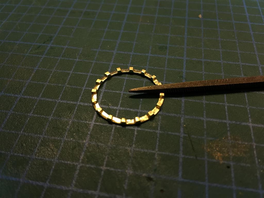
| I cut the pawl rim (ring) out of brass plate using a jeweler's coping saw. |
 |
| I filed each stop by hand, after carefully scoring the brass. |
 |
| The pawl rims were each made from pipe fittings flared to the precise diameter. |
 |
| The pawl rim prior to soldering and sanding. |
 |
| The piece following soldering. I used copper solder for the first time on this piece - despite being very dirty, it worked well. |
 |
| To maintain the proper curvature, I cut the pawls from a copper fitting. |
 |
| The pawls cut roughly to length. |
 |
| Bolt holes were drilled before shaping. |
 |
| Each pawl was filed and shaped by hand. |
 |
The completed pawl rim (ring) and pawls. Two traits unique to Phillips' capstans can
be seen here. First, the pawl rim was bolted through each stop, rather
than in the spaces. Second, Phillips' capstans had between six and
eight pawls, while earlier models typically had four. |
 |
| The pawlhead. |
 |
The completed pawlhead with the top plate soldered in place. Contemporary models show that the pawlheads on
Phillips' capstans were made entirely of iron. |
 |
| Dry fitting the metal pieces. The pawls need some thinning here. |
 |
| Pieces prior to finishing and assembly. |
 |
| Blackening the metal parts. |
 |
The metal pieces after blackening, buffing, and sealing
(I use Krylon matte coat as a sealer). |
 |
| The completed capstan. The wooden pieces have been treated with Minwax wipe-on poly. |
 |
| Detail of the pawl rim and pawls. |
 |
| The drumhead (the drop pins indicate it is in direct-drive mode). |
 |
| Detail of the lower drop pins (I couldn't find scale chain small enough to model that feature). |
 |
| Mini-Crozier inspects his capstan, recalling his good times with Parry. |
Of course, one further Phillips' patent capstan is known to
exist – on the wreck of HMS
Erebus.
Parks Canada’s recent
video
tours show that it is heavily damaged and that it is very obscured by the
growth of marine life. How it compares to my plans and model is impossible to
tell from the video, but hopefully my model isn't too inaccurate. If the historic plans
are any indication, any differences should be quite minor.
Footnotes:
1 Harland, John. 1999 Improved Capstans. Nautical Research
Journal 44(4): 214-220.
2: Parry, Sir William Edward. 1826. Journal of a Third
Voyage for the Discovery of a Northwest Passage- from the Atlantic to the
Pacific, Performed in the Years 1824-25, in His Majesty's Ships Hecla and Fury, Under the Orders of Captain William Edward Parry, R.N.,
F.R.S., and Commander of the Expedition. John Murray, publisher to the Admiralty,
and Board of Longitude. Page: 14.
3. (ibid, Page14)
4. The Mirror of
Literary, Amusement, and Instruction. 1825.
Page 451.
5. Encyclopaedia Britannica. 1854. Capstan. Pages 128-129,
Plate CXLVI.
6. American Magazine of Useful and Entertaining Knowledge,
Volume 3.Nathaniel Hawthorne, Elizabeth Manning Hawthorne, Boston Berwick
Company, 1837. Page 203.


