As I’ve documented in previous
posts, HMS Terror’s stern well was to be filled with strengthening chocks
when the propeller wasn't in use. A unique feature of this design was described
by Oliver Lang, the shipwright in charge of the 1845 refit, as an “iron tank
placed over the chocks in which any small article of stores may be stored” (NMM
ZAZ5683 [J1529]). Lang’s 1845
plan, while vague, suggests that the tank was similar to iron storage tanks
used in Royal Navy ships of the era, with one major difference: the fore and
aft faces of the tank had two grooves running along their length to seat it on
the rails in the propeller well (see my previous post).
 |
| Oliver Lang's 1845 design for the storage tank (right). National Maritime Museum, Greenwich, London (ZAZ5683 [J1529]). |
Iron tanks had been used in the Royal Navy since 1813 and were used to store all manner of dry and wet goods, and were often used as ballast tanks when stores were depleted or offloaded (Pearson 1992). An example of the types of tanks used in the Franklin era can still be found in the excellently preserved Dealy Island Storehouse, constructed by Captain Kellett of HMS Resolute. The storage tanks were iron, ca. 48 inches by 48 inches in size, with lines of rivets along the middle and alternate edges of each face and around their circular openings (Jane 1982: Figure 3, Figure 6). I copied this rivet pattern in my reconstruction of the Terror’s stern tank.
The openings of these tanks were sealed with a recessed cast iron lid, between 12 and 24 inches in diameter with a wire rod handle and a cork or wooden bung inserted into a circular opening in their centre (Pearson 1992:24). Maudslay, Sons, and Field, who were contracted to supply the engines installed in HMS Erebus and Terror (Battersby and Carney 2011:201), owned the patent to produce ship's tanks (Pearson 1992:25), and it is reasonable to assume that they built the custom stern tanks for the Franklin Expedition. If so, the "Maudslay, Sons, and Field" name should be stamped on the cast iron lids for the tanks, if they are ever found (e.g. Pearson 1992:26).
As can be
seen above, the profile dimensions of the Terror’s stern tank are shown on Lang’s
plan, as well as a general indication of the size and position of the lid and
two iron rings used to raise and lower the tank into position. The plans
indicate the tank had the following profile dimensions:
Height = 40 inches
Length (moulded) = 25 and ½
inches
I have
estimated, based on the distance between the stern frames, that the propeller
well and the tank were sided approximately 34 inches.
References:
Pearson,
Michael
1992 From Ship to the Bush: Ship Tanks in
Australia. Australasian Historical Archaeology 10: 24-29.
Janes, Robert R.
1982 The
Preservation and Ethnohistory of a Frozen Historic Site in the Canadian Arctic.
Arctic 35(3):358-385.
Battersby, William, and Carney, Peter
2011 Equipping HM Ships
Erebus and Terror, 1845. International
Journal for the History of Engineering and Technology 81(2):192-211.
 |
| Sheet brass scored prior to cutting. |
 |
| A pounce wheel was used to mark the location of the rivets. |
 |
| The rivets were simulated by punching the brass from the reverse side with the sharp end of a file. |
 |
| The central opening and wire handle of the lid were made from brass tube and wire. |
 |
| The outer rim of the lid was soldered into place. The central opening (right) was trimmed and soldered to a plate to form the bottom of the lid (wire still needs to be trimmed to length). |
 |
| The completed lid soldered in place and cleaned up (sanding is still required and the central hole needs to be drilled to remove the wire rod). |
 |
| Rings for raising and lowering the tank soldered in place. |
 |
| The tank parts after chemical blackening. The grooves were made from existing brass stock. |
 |
| Soldering the entire tank was impossible, so a balsa form was created to glue the plates in place. |
 |
| Starboard side glued in place. |
 |
| The finished tank. The seams were glued, sanded and then painted to match the metal surface. The piece was then lightly coated in dewatering oil to simulate the laquer often used on the real tanks (and to prevent future corrosion). |

 |
| Detail of the top of the tank. The bung in the lid was made with wood-filler. |
 |
| The approximate position where the tank will sit in the well. I'm waiting for the oil to fully penetrate before I dry-fit the piece to the wood. |
 |
| The tank seated on the propeller rails. When the rails are glued in place on the stern the tank can be placed in the well or on deck depending on how the model will be displayed (e.g. with propeller in place or not). |
 |
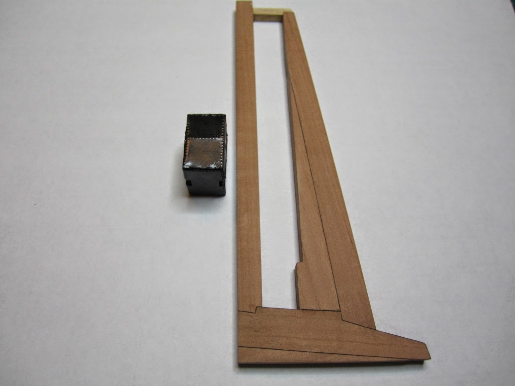
| A crude model of Captain Crozier provides a sense of scale. |
Fantastic work.
ReplyDeleteRegards
Thomas
Thank you Thomas!
ReplyDeleteImpressive - well done!
ReplyDeleteFantastic work! I love how intricate the work is for these smaller-scale models. If the ship is already small, the tank has to be even smaller. The work would be very delicate, indeed. What else are you trying to do with the Terror? Keep us posted!
ReplyDeleteBrandi Bradley @ Rotax Metals
Thank you so much for this wonderful blog.
ReplyDelete
ReplyDeleteCrypto Asset Recovery: Ethical and Transparent Cryptocurrency Recovery with Alpha Recovery Experts.
Hiring Alpha Recovery Experts to help me recover my stolen Bitcoin was one of the best moves I've ever made. From conducting thorough analyses of transaction trails to utilizing advanced tracing software, Alpha Recovery Experts swiftly identified potential leads and established connections with law enforcement agencies. Their planned approach resulted in the successful recovery of a major percentage of my lost assets, reinforcing the value of involving professionals in high-stakes digital scenarios. Without doubt, committing this difficult issue to Alpha Recovery Experts was a critical step in regaining control of my financial future. I urge all scam victims seeking assistance in recovering their lost cryptocurrency to reach out to Alpha Recovery Experts, a highly regarded expert in digital asset recovery.
Email: Alpharecoveryexpert@consultant.com or WhatsApp at : +44(745)742-4681
Website link; Alpharecoveryexperts.com